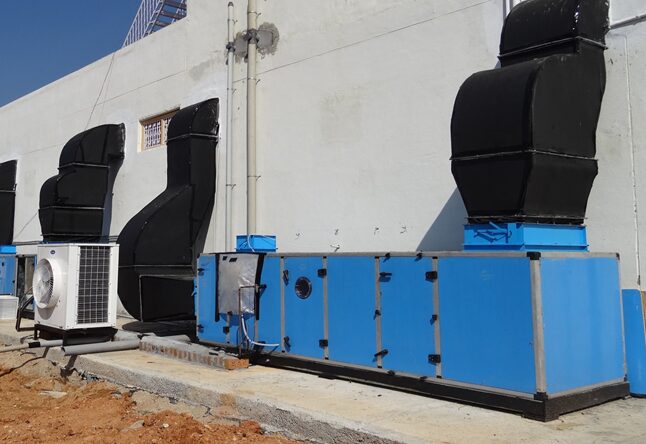
Air Handling Unit: Key and Best Practices of Technical Submittals

Packaged Air Handling Unit with Blowers, Cooling Coil, and Filters

The packaged air handling unit (AHU) shall be factory assembled units in factory fabricated casings. Each unit shall be complete with aerofoil centrifugal blowers, motors, drives and guards, cooling coil and drain pans, air filters, structural mountings, vibration isolators and all other necessary accessories. The units shall be tested, rated and constructed in accordance with relevant ARI standard, ASHRAE Standard and America Safety Code B91. The blowers and cooling coils of the units shall have the specifications and capacity ratings as states in the technical schedule.

Air Handling Unit

AHU Casing

The casing shall be fabricated from the best quality corrosion resistance electron-galvanized sheet steel and finished externally with oven-baked-on paint. It shall be properly reinforced and braced for rigidly with steel angle. The casing shall be made up in sections to accommodate the fan, the coil, condensate tray and the filters. Mating joints shall be flanged and bolted together with 1/8” thick gaskets to form a continuous air tight seal. Housing shall be supported from floor or ceiling as indicated in the drawings. The casing shall be double-skinned lined internally with corrosion resistance GI sheet to prevent condensation and control noise emission. Insulation material sandwiched between the doubled skinned panel shall be either 2 inches, 24 kg/m3 fibreglass or equivalent injected (thermal and acoustically) foam having a spread of flame index not greater than 0 and a smoked developed index not greater than 3 when tested on exposed face in accordance with AS 1530.3. Prior to the fixing of insulation all casing shall be treated with an approved anti-corrosive treatment. Condensation on any external parts of the casings will not be permitted. Install insulation in such a manner as not to be disturbed if panels are removed. Secure insulation to the casing surfaces and framework with adhesive over the entire surface. Cover insulation with inner casing wall. Neoprene coated fabric shall be used to connect the unit to the ductwork. Each unit shall be mounted on spring isolators. Ceiling hung units shall be mounted on a rigid steel channel or angle frame with shall then be suspended from hanger rods through spring isolators. External galvanised sheet steel shall be of 1.6mm (16 gauge) thick and the internal wall shall be constructed of galvanised sheet steel of 0.6mm (24 gauge) thickness. Fully gasket individual unit sections between flanged joints and fasten together with lock boilers, nuts and bolts to produce an airtight assembly.

Blower and Blower Sections of Air Handling Unit

The blowers of each air-handling unit shall be double width, double inlet and of centrifugal airfoil type. The whole blower, shaft and motor assembly shall be statically and dynamically balanced to ISO quality grade G6.3 and complete with matching housing, Bearings shall be heavy duty self-aligning ball type amply sized for the loads with factory-sealed lubrication and with provisions for re-lubrication externally thru grease nipples. The ball bearing shall be designed for a life not less than 50,000 hours. (ISO B10, 90 survival). The blowers shall be vee-belt driven (minimum 2 belts) by a squirrel-cage type high efficiency A.C induction motor. The vee-belt shall be able to withstand 1.5 times the duty requirement. Motors must be constructed with totally enclosed fan cooling. Motors shall be suitable for 415 volts, 3-phase, 50 cycle supply and 1450 rpm designed for continuous operation. Appropriate starter to comply with TNB Regulation shall be used to limit the in-rush starting current. A method of motor mounting giving full belt adjustment shall be incorporated. The maximum outlet velocity of the blowers shall not exceed 2200 fpm. The blower section shall be manufactured of heavy gauge galvanised steel or aluminium angle members securely bolted and braced with galvanised steel panels. The panels shall be double-skinned insulated with 50mm minimum thickness of neoprene coated fibreglass insulation with a density of not less than 2.0 1b/ft3 and faced with perforated mate face. The casing and all accessories shall be given a protective enamel finish. All metal parts of the units shall be chemically cleaned, phosphatised and coated with oven-baked enamel finish.

Cooling Coils and Coil Sections

The cooling coils of each air-handling unit shall be of cartridge type, removable from either side of casing and supported the entire length in tracks. All coils of more than one row deep should be provided with staggered tube pattern. The coils shall constructed of copper tubes and have a minimum outside diameter of 5/8 ins. tubing shall be individually finned with corrugated aluminium or copper ins warrant under tension and having not less than fins per inch and not more than 12 fin per inch. There shall be minimum of 6 rows of interlaced copper tube to cool and dehumidify the total air-flow. Fin design shall be suitable for operation up to 600 fpm face velocities without moisture carrying over. The maximum design face velocity shall be 550 fpm or less. The coils fitted with the headers shall have a suitable distribution network designed to provide uniform distribution of chilled water over the face of the coils. All coil tube joints must utilize high-temperature brazing alloys. The coils shall be designed for a maximum working condition of 300 psig for cooling. Coil section shall be manufactured the same as the fan section. Coil section with cooling coils shall have drain pan constructed of heavy gauge stainless steel sloped towards centre and with drain connection on the side. The exterior of pan shall be adequately insulated to prevent condensation being formed on the outside.

Face and Bypass Damper

Face and bypass dampers shall be fitted to the all Cinemas AHUs. The damper blades shall be opposed acting type with damper contact rod rotating on nylon bushes and mounted in a rigid galvanised steel damper frame. Each of the Face and Bypass damper shall consist of two sets of dampers, the face damper and the bypass damper. The face damper shall be located directly in front of the cooling coil and the bypass damper shall be located above the coil. This arrangement permits air to bypass the cooling coil for part load control. When one of the dampers is fully opened the other should be fully closed. The bypass arrangement reduces the capacity of the coil by decreasing the amount of air passing over the coil. However, as air flow through the coil is decreased, the remaining fan CFM passes through the bypass to maintain a constant air volume to the air distribution system. This face and bypass damper shall be from the AHU manufacturer. Dampers assembly must be approved by the Consultant before manufacturer to ensure they air of heavy duty type and withstand the operating condition. On application employing face and bypass section, the fan selection and air distribution system must be designed for an air quantity 10% above design dehumidified air volume. This additional air quantity compensates for leakage through a fully closed bypass damper and for air quantity variations when the dampers are in intermediate positions. Dependable heavy duty motorized damper motor shall be installed which shall be activated by a temperature controller installed at the returned end. An off-coil temperature sensor shall be installed after the coil to maintain a constant off-coil temperate by modulating the proposed two-way control valve. The operation shall be Proportional and Integral for optimum control of room temperature and humidity.

Air Handling Unit Filters

Pre-filters and secondary filters shall have an A.F.I dust extraction efficiency of not less than 75% and 95% respectively. Pre-filters shall be of the washable type while secondary filters may be of the disposable or washable type. They shall be arranged in sufficient numbers to operate at the correct manufacturer’s rating. The filters shall be supported on both sides by 12 gauge wire mesh or not more than 4 ins. square in a filter frame of rust proof construction of 18 gauge steel. The filter frame shall consist of an outer section and a quick release removable gate section from which the filter only can be removed for changeover and/or washing. Each A.H.U. shall have 2 stage filter located before the coil.

Vibration Isolators

Factory engineered spring isolators shall be provided with neoprene in double deflection with the optimum deflection for the loading. Suitable mounting channels shall be provided for floor mounting use with the vibration isolators.

Insulation

The blower and cooling coil sections shall be internally insulated and vapour sealed with mastic compound or equivalent.

Condensate – Drip Tray

A suitable designed durable rust proof stainless steel drip tray shall be provided with each air-handling unit. It shall be insulated with sufficiency designed thick PE insulated sheet to prevent condensation and sweating. The drip tray shall be graded to a drain pipe extended throw the unit casing. The drain pipe shall be minimum 32 mm the trapped drain design shall ensure correct condensate drainage and maintain a water seal during unit start-up and operation. Calculation shall be submitted to substantiate the water seal properties.

Technical Submittal Requirements

The following information is to be included and shall form the basis of the shop drawing submittal.

The listed information is to be provided for each unit type and size:

  • Detailed construction specification sheets.
  • Manufacturer’s latest published data for dimensions, materials, accessories and installation details.
  • Full technical rating data based on tests in accordance with current AMCA standards. Include manufacturer’s certified fan performance curves, and certified sound power ratings. Correct all ratings and curves for altitude and temperature.
  • Factory test reports initiated by technician who performed test.
  • Certified fan performance curves indicating volume- pressure-speed-horsepower characteristics from shut off the free delivery.
  • Certified sound power ratings with octave band analysis.
  • The type and size of fans being provided.
  • The fan motor kW and electrical power characteristics.
  • The fan brake kW per unit at:
    • 100% flow
    • Specified conditions
    • 80% flow (maintaining external static)
    • 60% flow (maintaining external static)
    • Minimum flow (state minimum air flow as % of specified flow)
  • Technical data for the motor, including manufacturer’s name and location.
  • Plans, elevations and sections of the unit, dimensioned in inches and in millimetres showing clearance required on each side and top of unit as well as the location and access to the following components:
    • Fan motor drive, belts, bearings
    • Cooling coils
    • Filters
    • Construction of access panels and method of fastening.
  • Unit control diagrams.
  • Operating, maintenance, and service instruction and manuals.
  • Single line electrical diagrams of all wiring internal to unit.

Quality Assurance

Construct units in compliance with all requirements of the latest edition of the Air Movement and Control Association’s (AMCA) certified rating standards for air moving equipment.

Test, rate and certify unit’s performance characteristics, including cooling coils.

Filters shall be U.L. listed.

Rate filter efficiency, as measured by the Atmospheric Dust Spot Efficiency Test, weight arrestance and dust holding capacity in accordance with the test procedures of ASHRAE Standard 52.

All components shall comply with Fire for flame spread and smoke develop characteristics.

To know more about Net Zero Energy Building HVAC Systems Click Here

Site Execution of Air Handling Unit

Installation

Install as per manufacturer’s recommendations and as shown on drawings. Follow SMACNA recommended procedures.

Manufacturer shall provide supervisory, testing, and start-up personnel as required.

Provide flexible connections to prevent separation of equipment from ductwork and to prevent metal to metal contact.

Install air handling units with proper support and vibration isolation as specified in section entitled ‘Vibration Isolation’.

Provide sufficient clearance around equipment for access and servicing of equipment and its components. Install equipment such that fans, coils, valves, access doors, filter, electrical components, etc. are readily accessible and unobstructed.

Bump start fans to check that fan wheel rotation is correct. For fans not rotating in proper direction, correct them.

Tighten and align belts, taking into account design of drive. Do not over tension belts.

Check all belts and fasteners to ensure proper tightness.

Check bearings and motor for lubrication; do not over lubricate. Use lubricants recommended by manufacturer.

Connect all chilled water and drain piping to unit in approved way and in accordance with drawings.

Acoustical Acceptance Test

General

Air handling unit shall be subject to a full scale mock-up test demonstration, witnessed by Employer’s representatives. The Manufacturer must demonstrate, as per the following specification, that the specified sound level as defined in the ‘Schedule of the Noise level of the Designated Room’ is achieved.

The test set-up shall be conducted at the manufacturer plant or at the project building, which will be constructed by the Contractor. Delivery and set up of the AHU, including ductwork construction inside of the fan room, electrical connections, and any other necessary work, shall be conducted by the Manufacturer or its designated representatives.

Air Handling Unit

The test unit shall be standard manufactured equipment, able to deliver the design air flow against the design external static pressure and shall be shown in the schedules in the design drawings, satisfying all specified requirements explained elsewhere in this specification. The unit must be tested with a temporary 50Hz power source, 415 Volts, arranged by the Contractor.

The variable speed control device, fan motor, and all related electrical components, shall be identical models, and shall be mounted in the cabinet exactly as units shall be sent for the project. Substitution or remote placement of any such components for the purpose of the test shall not be acceptable. Provide 19mm thick waffled neoprene pad isolators to be installed beneath the structural supports.

To know more about AHU Specifications Exploring What You Need to Know Click Here

Ductwork Construction Inside of Fan Room

The Contractor shall supply ductwork connection from the AHU discharge to the point where the duct exist the fan room. Supply ductwork out of the fan room shall be constructed and shall be shown on the design drawing, to provide optimum airflow conditions and sound attenuation. The supply ductwork shall be constructed per SMACNA standards.

Internal acoustical lining should be provided in ductwork. In the AHU supply plenum, acoustical duct lining as specified in “Casings” should be used; and the remainder of the ductwork is to be lined with 25mm thick, mat faced, 24 kg/m3 (1½ lb/ft3) fibreglass duct liner. The manufacturer shall submit drawings showing the fan room layout, with the intended AHU and ductwork configuration, for review by the Employer and the Consultant.

Test Procedures for Air Handling Unit

  1. The manufacturer shall furnish qualified technicians and the approved Acoustical Consultant appointed by the Contractor to assist the Employer and the E.R Acoustical performance tests shall be conducted as follows:-
  2. Test unit shall be balanced to deliver design air quantities at design discharge pressures.
  3. Air quantities shall be verified by taking air velocity traverses across ductwork.
  4. Motor amperage draw and fan RPM shall be recorded for verification of fan performance with the fan curve.
  5. Noise measurements in the test rooms shall be performed by the approved Acoustical Consultant appointed by the Contractor who will search for the peak sound pressure levels and establish a reasonable average at each octave bank frequency.
  6. The test air handling unit will then the throttled back by means of the unit’s variable volume control device to deliver 80% and 60% of full air flow. While maintaining the same discharge duct static pressure. (Downstream damper positions will be varied to provide the necessary resistance at the various airflow conditions). Intermediate steps in the fan speed will be subjectively evaluated to verify that the fan noise does not exhibit any “tonal” characteristics at any fan operating speed.
  7. Repeat steps (2) through (4) at each air quantity setting.
  8. Test measurements will be plotted on Noise Criterion curves to establish the test unit’s acoustical performance based on Noise Criterion ratings.

Acceptance Criteria for Air Handling Unit

Manufacturers are encouraged to design and construct their equipment to perform with the lowest Noise Criterion levels, when tested in accordance with procedures specified herein. Suitable internal design features and optimum discharge duct configuration should be incorporated to minimise noise transmitted to the test rooms.

If the manufacturer’s unit performs with noise levels measured in the test room exceeding the designed sound level pressure levels for the office area served.

Conclusion

In conclusion, the specified packaged air handling unit (AHUs) are designed for optimal performance, durability, and efficiency. Each unit is factory-assembled with high-quality materials, including corrosion-resistant steel and advanced insulation, to prevent condensation and reduce noise. Components such as centrifugal blowers and cooling coils are meticulously tested and rated to meet industry standards. The inclusion of face and bypass dampers, high-efficiency filters, vibration isolators, and condensate drip trays ensures effective air control and high air quality. The detailed technical and quality assurance requirements, along with rigorous acoustical testing, guarantee that the AHUs will perform reliably while maintaining compliance with all operational and safety standards, making them a valuable addition to any HVAC system.

About The Author

Omprakash Ramagiri; as the Founder of HVAC Technocrats, I bring over 18 years of experience as a Mechanical Engineer specializing in HVAC (Central Air-conditioning) for commercial, cleanrooms, data centers, and Petrochemical industries. Throughout my career, I’ve held pivotal roles at companies like TATA Consulting Engineers, MW Zander (for Cleanroom solutions), Bluestar Malaysia, and ETA in Dubai. I’ve managed international HVAC projects and gained valuable exposure in dynamic markets like Dubai and Saudi Arabia. With a passion for excellence and a commitment to innovative solutions, I specialize in designing Class 10K & 100K Cleanrooms for various industries. Connect with me to explore collaborations in HVAC design, project sales, and consultancy. Click to visit the Author’s Linkedin page


Disclaimer: The content and images are for educational purposes and knowledge enhancement only. They may not depict actual products or situations. Outcomes may vary. Content is generated by AI and reviewed by industry experts, including Author.

Petrochemical: When to Perform Energy Audits for HVAC Systems

Diagram illustrating energy audits for HVAC systems in petrochemical facilities.

Understanding when to perform energy audits for Petrochemical HVAC systems is critical to optimizing energy efficiency, reducing operating costs, and ensuring environmental friendliness. This article examines the timing of these audits, their benefits, and best practices for implementation in the petrochemical industry.

Conducting Energy Audits for Petrochemical HVAC Systems

Performing energy audits for petrochemical HVAC systems is essential to maintaining optimal energy efficiency and reducing operating costs. Regular audits help identify areas of energy waste and recommend improvements to improve system performance. This article explores the best time to perform these audits and provides information on the benefits and methodology involved.

What is energy audit in Petrochemical for HVAC system?

An energy audit on an HVAC system is a thorough investigation of the system’s energy consumption and efficiency. It involves assessing current energy consumption, identifying inefficiencies, and recommending improvements. These audits help identify areas where energy savings can be achieved, ensuring that the HVAC system is operating at its maximum efficiency.

What is the role of an energy audit in petrochemical HVAC systems?

The primary role of an energy audit in petrochemical HVAC systems is to improve energy efficiency and reduce operating costs. These audits identify inefficiencies and suggest actions to improve system performance. They also help maintain compliance with environmental regulations and industry standards, ensuring sustainable and cost-effective operations.

Why perform an energy audit on petrochemical HVAC systems?

Performing an energy audit on petrochemical HVAC systems is important for several reasons:

  • Energy efficiency: Identifying and resolving energy waste.
  • Cost reduction: Helps reduce operating costs by optimizing energy consumption.
  • Compliance: Ensures compliance with environmental regulations and industry standards.
  • System longevity: Extends the lifespan of the HVAC system while maintaining optimal performance.
  • Sustainability: Promotes sustainable practices by reducing the carbon footprint.
  • Where to apply an energy audit in a petrochemical HVAC system?

    Energy audits should be applied to various aspects of petrochemical HVAC systems, including:

  • Air handling units: Assessing the efficiency of air handling units and their components.
  • Ventilation systems: Evaluating the performance of ventilation systems to ensure proper air flow.
  • Cooling towers: Checking the efficiency and condition of cooling towers.
  • Piping and ductwork: Inspecting piping and ductwork for leaks and insulation problems.
  • Control systems: Analyzing the effectiveness of control systems in managing energy consumption.
  • How to conduct an effective energy audit?

    Effective energy audits in petrochemical HVAC systems can be achieved through several strategies:

  • Regular monitoring: Continuous monitoring of energy consumption to identify trends and anomalies.
  • Detailed inspection: Comprehensive inspection of all HVAC components to assess their condition and performance.
  • Data analysis: Analyzing energy consumption data to identify inefficiencies and recommend improvements.
  • Staff training: Staff training on best practices for energy management and system maintenance.
  • Advanced instrumentation: Using advanced instrumentation and techniques for accurate measurements and analysis.
  • What are the latest techniques in energy audits?

    Latest techniques in energy audits for petrochemical HVAC systems:

  • Real-time monitoring system: Provide continuous data on energy consumption and system performance.
  • Advanced sensors: High efficiency sensors for accurate measurement of energy consumption.
  • Thermal Imaging: Detects areas of energy loss through thermal imaging.
  • AI and Machine Learning: AI-powered tools for predictive maintenance and energy optimization.
  • Smart Meter: Advanced metering system for accurate energy consumption tracking.
  • What are the advantages and disadvantages of an energy audit?

    Benefits:

  • Improved Efficiency: Improves the overall efficiency of the HVAC system.
  • Cost savings: Reduces operating costs through energy optimization.
  • Compliance: Ensures compliance with regulations and standards.
  • Sustainability: Promotes sustainable energy practices.
  • System Longevity: Extends the lifespan of the HVAC system.
  • Disadvantages:

  • Initial cost: Energy audit is expensive in the beginning.
  • Maintenance: Continuous maintenance and monitoring is required for continuous benefit.
  • Complexity: Implementation of recommended actions is complex and time consuming.
  • What Are the Key Components of an Energy Audit?

    An energy audit includes several key components:

  • Pre-audit preparation: Collect relevant data for the audit and determine the objective.
  • Site Inspection: Physical examination of the HVAC system and its components.
  • Data collection: Measure energy consumption and performance metrics.
  • Analysis: Identifying inefficiencies and possible improvements.
  • Reporting: Documenting findings and recommendations for energy savings.
  • How to prepare for an energy audit?

    Preparation is key to an effective energy audit. The steps include:

  • Data collection: Historical energy consumption data and system documentation are collected.
  • Team Coordination: Assembling a team of experts to conduct the audit.
  • Objective Determination: Defining the objectives and scope of the audit.
  • Scheduling: Planning the audit to minimize disruptions to operations.
  • Communication: Informing stakeholders about the audit process and expected results.
  • What are best practices for energy audits?

    Best practices for conducting an energy audit:

  • Comprehensive evaluation: Ensure that all components of the HVAC system are thoroughly checked.
  • Stakeholder Participation: Involving all relevant stakeholders in the audit process.
  • Detailed Documentation: Keeping a detailed record of findings and recommendations.
  • Follow-up: Implement recommended actions and monitor their effectiveness.
  • Continuous improvement: Regular review and updating of energy management practices.
  • How often should an energy audit be done?

    Energy audits should be conducted regularly to ensure ongoing efficiency and compliance. The best practice suggests:

  • Annual Audit: Conduct a comprehensive audit at least once a year.
  • Interim Review: Interim reviews quarterly or semi-annually.
  • Event-Driven Audit: Schedule an audit after a significant change or upgrade to the HVAC system.
  • What are the costs associated with energy audits?

    The costs associated with energy audits can vary based on a number of factors, including:

  • Scope of Audit: A more extensive audit may require more investment.
  • Size of facility: Larger facilities generally cost more.
  • Complexity of systems: Complex HVAC systems may require specialized expertise and equipment.
  • Implementation of Recommendations: Costs may also include investments in recommended improvements and upgrades.
  • How to measure the success of an energy audit?

    The effectiveness of an energy audit can be evaluated by:

  • Energy saving: Quantitative reduction in energy consumption.
  • Cost savings: Reduction in operating cost as a result of better efficiency.
  • Compliance: Adherence to environmental regulations and industry standards.
  • System performance: Better performance and longevity of the HVAC system.
  • Sustainability target: progress towards sustainability and carbon reduction targets.
  • FAQ

    What is the purpose of an energy audit in petrochemical HVAC systems?

    The primary purpose of an energy audit in petrochemical HVAC systems is to identify and resolve energy inefficiencies. These audits help reduce operating costs, ensure compliance with environmental regulations, and promote sustainable practices.

    How can energy audits improve the efficiency of HVAC systems?

    Energy audits improve the efficiency of HVAC systems by identifying areas of energy waste and recommending actions to optimize energy use. This includes upgrading components, improving maintenance practices, and implementing advanced control systems.

    What are the common methods used in energy audits for HVAC systems?

    Common methods used in energy audits for HVAC systems include real-time monitoring, thermal imaging, data analysis, and detailed inspections. These techniques help identify inefficiencies and recommend improvements.

    Why is continuous monitoring important in energy audits?

    Continuous monitoring is crucial in energy audits as it provides real-time data on energy consumption and system performance. This enables early detection of inefficiencies and timely implementation of corrective actions.

    What are the challenges in conducting energy audits for petrochemical HVAC systems?

    Challenges in conducting energy audits for petrochemical HVAC systems include high initial costs, complexity in implementing recommended measures, and the need for continuous maintenance and monitoring. Despite these challenges, the benefits of improved efficiency, cost savings, and compliance make energy audits imperative.

    Conclusion

    Conducting energy audits for petrochemical HVAC systems is essential to maintain optimal efficiency and reduce operational costs. These audits help identify inefficiencies, ensure compliance with regulations, and promote sustainable practices. By implementing effective energy audit strategies, industries can improve the performance and longevity of their HVAC systems, ultimately resulting in cost savings and improved operational efficiency.

    About The Author

    Omprakash Ramagiri; as the Founder of HVAC Technocrats, I bring over 18 years of experience as a Mechanical Engineer specializing in HVAC (Central Air-conditioning) for commercial, cleanrooms, data centers, and Petrochemical industries. Throughout my career, I’ve held pivotal roles at companies like TATA Consulting Engineers, MW Zander (for Cleanroom solutions), Bluestar Malaysia, and ETA in Dubai. I’ve managed international HVAC projects and gained valuable exposure in dynamic markets like Dubai and Saudi Arabia. With a passion for excellence and a commitment to innovative solutions, I specialize in designing Class 10K & 100K Cleanrooms for various industries. Connect with me to explore collaborations in HVAC design, project sales, and consultancy. Click to visit the Author’s Linkedin page


    Disclaimer: The pictures used are for illustrative purposes only. They may not depict actual products or situations and are meant for educational purposes. Actual products, situations, or outcomes may differ.

    How to Reduce HVAC Energy Consumption in Petrochemical Operations

    Discover effective strategies to reduce energy consumption in HVAC systems in petrochemical facilities, leading to significant cost savings and environmental benefits.

    Minimizing Energy Consumption in Petrochemical HVAC Operations

    Petrochemical operations require strict environmental regulation to ensure safety and productivity. HVAC systems are the most important but can be significant energy consumers in these facilities. By adopting strategic measures, energy consumption can be significantly reduced, resulting in lower operational costs and a reduced carbon footprint.

    Understanding HVAC Systems in Petrochemical Operations

    HVAC systems manage air quality, temperature and humidity in petrochemical operations. These systems include air handling units (AHUs), chillers, cooling towers and ductwork. Efficient operation of these components is essential to reduce energy consumption.

    Key strategies to reduce HVAC energy consumption

    Optimizing Air Changes Hourly (ACPH)

    Balancing ACPH is critical in petrochemical environments. Too much ACPH leads to unnecessary energy consumption, while too little compromises air quality. Calculating the optimal ACPH based on specific operational requirements can result in significant energy savings.

    Using variable air volume (VAV) systems

    VAV systems adjust airflow based on current load, reducing energy consumption. In contrast to constant air volume systems, VAV systems can reduce fan speed and reduce the need for cooling and heating to adapt to changing environmental conditions.

    Implementation of Energy Recovery Ventilators (ERVs)

    ERVs capture energy from the exhaust air and transfer it to the incoming fresh air, reducing the energy required to condition the incoming air. It is particularly useful in petrochemical operations where ventilation demands are high.

    Leveraging advanced controls and automation

    Smart HVAC controls can optimize system performance by adjusting settings in real time based on environmental data. Automation systems can integrate with building management systems to ensure that HVAC components operate only when needed, reducing energy waste.

    Improving insulation and sealing

    Proper insulation of ducts and sealing of leaks prevents the loss of conditioned air, ensuring that the HVAC system operates efficiently. This is particularly important in large petrochemical facilities where ductwork spans considerable distances.

    Pros and cons of energy-efficient HVAC systems

    Pros:

    • Reduced energy costs: Lower energy consumption results in significant cost savings.
    • Environmental benefits: Reduced energy consumption reduces carbon footprint.
    • Better system longevity: Efficient systems experience less wear and tear, leading to longer lifespans.
    • Improved air quality: Optimized systems can better handle pollutants and ensure clean air.

    Cons:

    • Initial Investment: Upgrading to energy-efficient systems requires significant upfront costs.
    • Maintenance Requirements: Advanced systems may require more routine maintenance and skilled personnel.
    • Technology Dependency: Relying on automated systems requires strong IT support.

    FAQ

    What is the role of HVAC systems in petrochemical operations?

    HVAC systems play a critical role in maintaining safe and productive environments in petrochemical operations. They control temperature, humidity and air quality, ensuring the facility operates in optimal conditions. Properly functioning HVAC systems also help prevent the build-up of hazardous gases and ensure compliance with safety regulations.

    How can VAV systems reduce energy consumption?

    VAV systems reduce energy consumption by adjusting airflow based on current demand. Unlike constant air volume systems that operate at a fixed rate, VAV systems can modulate airflow, reducing fan speed when full airflow is not required. This can lead to significant energy savings, especially in large facilities with varying occupancy levels.

    Why are ERVs important in petrochemical HVAC systems?

    ERVs are important in petrochemical HVAC systems because they recover energy from the exhaust air and use it to precondition incoming clean air. This process reduces the load on heating and cooling systems, leading to lower energy consumption. ERVs are particularly beneficial in facilities with high ventilation requirements, as they improve overall energy efficiency.

    What are the benefits of smart HVAC controls?

    Smart HVAC controls offer many benefits including optimized system performance, reduced energy waste and improved efficiency. These controls use real-time data to adjust settings, ensuring that HVAC systems operate only when needed. This not only saves energy but also extends the lifespan of HVAC components by reducing unnecessary wear and tear.

    How does proper insulation affect HVAC efficiency?

    Proper insulation is critical to HVAC efficiency, as it prevents loss of conditioned air. In petrochemical facilities, where ductwork is extensive, insulation ensures that the air distributed to the various zones remains at the desired temperature. This reduces the load on HVAC systems, leading to lower energy consumption and more stable indoor conditions.

    Conclusion

    Reducing HVAC energy consumption in petrochemical operations is essential for cost savings and environmental sustainability. Petrochemical facilities can achieve significant energy reductions by optimizing ACPH, using VAV systems, implementing ERVs, increasing advanced controls, and improving insulation. Although the initial investment is high, the long-term benefits far outweigh the costs, making energy-efficient HVAC systems a smart choice for the petrochemical industry.

    Why PLCs Are Important for HVAC Equipment Automation

      Understanding the Role of Programmable Logic Controllers (PLCs) in HVAC Automation

      In the HVAC equipment industry, programmable logic controllers (PLCs) play an important role in streamlining operation and increasing efficiency It is important to understand their importance and applications for the optimization of HVAC systems breed.

        What is a programmable logic controller (PLC) in an HVAC system?

        Programmable logic controllers (PLCs) are specialized industrial computers designed to control machinery and processes, including those in heating, ventilation, and air conditioning (HVAC) systems that perform specific tasks based on conditions that insertion controls are included, making them important components of HVAC automation.

        What is the role of a programmable logic controller (PLC)?

        The main role of PLC in HVAC equipment automation is to monitor and control various system components such as pumps, fans, valves and sensors. By receiving input signals and preprogramming commands, the PLC ensures accurate control of temperature, humidity, ventilation, and other parameters necessary for optimal HVAC performance

        Where should programmable logic controllers (PLCs) be used / applications?

        PLCs find a wide range of applications in a variety of HVAC environments, including commercial buildings, industrial buildings, data centers and hospitals and residential complexes. They are instrumental in regulating temperature, humidity, and air quality while improving energy efficiency and operational reliability.

        How To Use The Programmable Logic Controllers (PLC)?

        Using PLCs in HVAC automation involves programming them to perform specific functions according to system requirements. This includes configuring input and output devices, creating logical sequences, and implementing control strategies tailored to the unique needs of each application.

        What Are The Advantages & Disadvantages Of Programmable Logic Controllers (PLC)?

        Pros:
        • Flexibility in programming and customization
        • Enhanced system reliability and uptime
        • Real-time monitoring and diagnostics capabilities
        • Incorporating with Building Automation Systems (BAS) to achieve centralized control.
        • Simplified troubleshooting and maintenance procedures
        Cons:
        • Initial setup and programming complexity
        • Dependency on skilled technicians for installation and maintenance
        • Potential for cybersecurity vulnerabilities if not adequately secured
        • Higher upfront costs compared to conventional control systems

        How To Install The Programmable Logic Controllers (PLC)?

        Installing PLCs in HVAC systems requires expertise in electrical wiring, device mounting, and programming. It involves mounting the PLC hardware, connecting input and output devices, configuring communication networks, and programming the control logic using specialized software.

        What Are The Supporting Details For Programmable Logic Controllers (PLC)?

        To ensure optimal performance and longevity of PLC-based HVAC automation systems, regular maintenance, software updates, and cybersecurity measures are essential. Additionally, ongoing training for personnel responsible for system operation and maintenance is crucial to maximize efficiency and minimize downtime.

        FAQ

          What is the function of programmable logic control in automation?

          Programmable logic controllers (PLCs) serve as the brain of automation systems, executing predefined logic commands to control machinery and processes. They monitor input signals, make decisions based on programmed instructions, and actuate output devices to achieve desired automation outcomes.

          Why are programmable logic controllers important?

          PLCs are vital in automation due to their ability to precisely control industrial processes, enhance operational efficiency, and improve system reliability. They facilitate seamless integration of various components, enable real-time monitoring, and streamline maintenance procedures, thus contributing to overall productivity and cost-effectiveness.

          What is PLC programming?

          PLC programming involves writing and implementing sets of instructions, known as ladder logic or function blocks, to define the behavior of a programmable logic controller. This programming dictates how the PLC processes input signals, executes logical operations, and generates output commands to automate specific tasks.

          How is PLC used in HVAC?

          PLCs are utilized in HVAC systems to automate control functions such as temperature regulation, airflow management, and equipment operation. They receive input signals from sensors, process data based on programmed logic, and adjust system parameters accordingly to maintain desired environmental conditions efficiently.

          HVAC PLC program example?

          An HVAC PLC program example could involve regulating the operation of a chiller unit based on temperature setpoints. The PLC would receive input from temperature sensors, compare it with the desired setpoints, and control the chiller’s compressor and valves to maintain optimal cooling levels.

          What is the working principle of PLC?

          The working principle of PLC revolves around scanning input signals, executing programmed logic, and generating output commands in a cyclical manner. PLCs continuously cycle through these processes, updating system states based on input conditions and executing control functions to automate industrial processes effectively.

          What is the full form of PLC?

          PLC stands for Programmable Logic Controller.

          What are the types of PLC?

          Types of PLCs include modular PLCs, compact PLCs, rack-mounted PLCs, and programmable automation controllers (PACs). Each type offers different form factors, processing capabilities, and expansion options to suit various automation applications and requirements.

          What is HVAC programming training?

          HVAC programming training involves learning how to program and configure PLCs specifically for HVAC system automation. It covers topics such as ladder logic programming, sensor interfacing, control algorithms, and troubleshooting techniques tailored to the needs of HVAC automation in commercial and industrial settings.

          What is PLC in electrical?

          PLC in electrical refers to the application of programmable logic controllers in electrical control systems. PLCs are used to automate electrical processes, monitor power distribution, control machinery, and implement safety interlocks, offering efficient and reliable control solutions in various electrical applications.

          Conclusion

          In conclusion, Programmable Logic Controllers (PLC) play a vital role in automating HVAC equipment, offering precise control, enhanced reliability, and energy efficiency. Understanding their application and leveraging their capabilities is key to optimizing HVAC systems for various commercial, industrial, and residential settings.