hvactechnocrat.com
- Clean Rooms , HVAC
- February 16, 2026
- 20 views
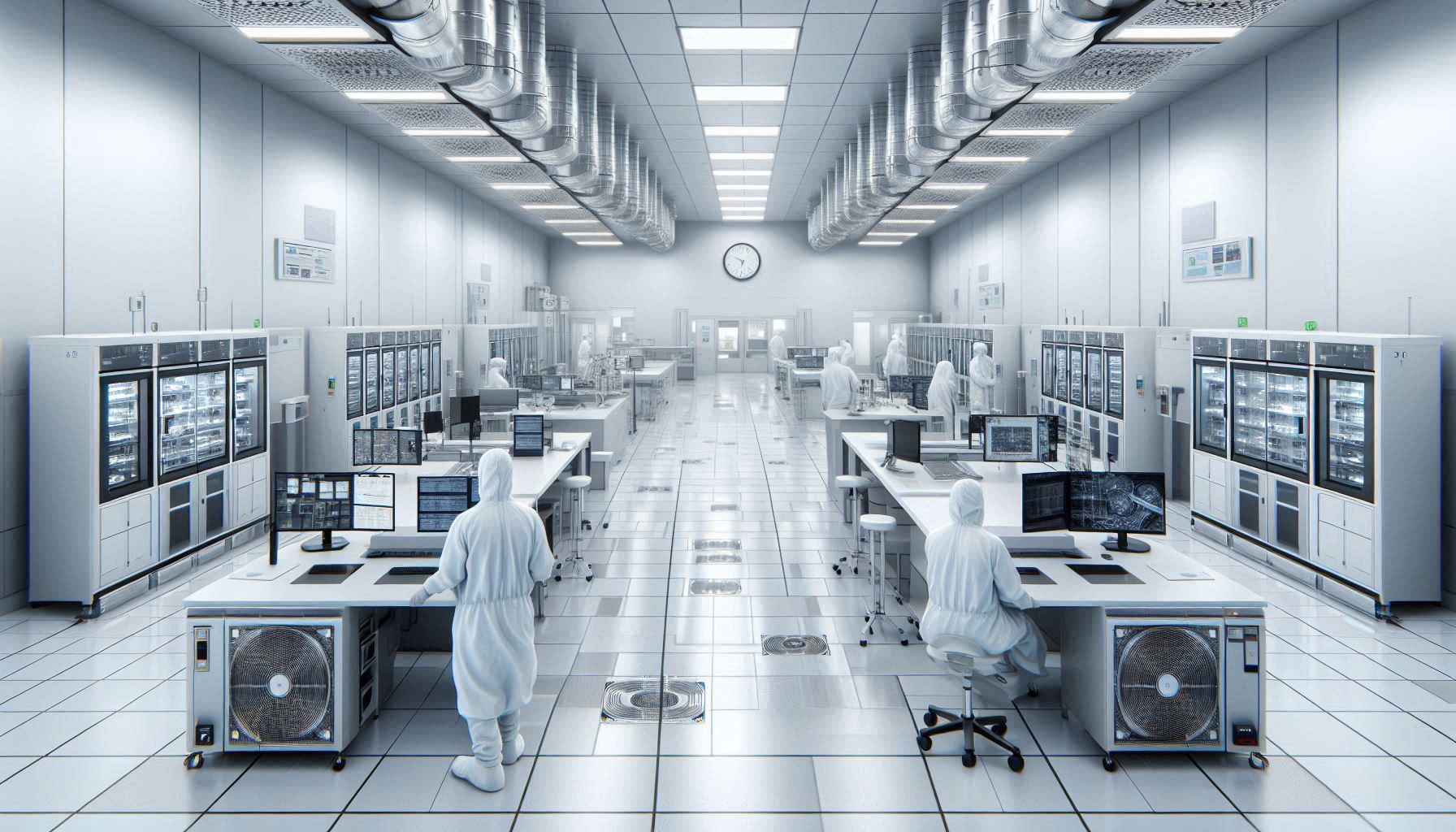
Semiconductor Wafer HVAC: Air Handling Unit Specifications & Best Practices
Semiconductor wafer processing recirculating air units form the backbone of modern wafer fabrication facilities. These specialized systems maintain ultra-clean environments through continuous air filtration and precise temperature control. Cleanroom RAU…

- Clean Rooms
- July 3, 2025
- 23 views
Cleanroom MAU Design for Semiconductor Industry
Make-up Air Units MAU Design for Semiconductor Industry represent the backbone of semiconductor cleanroom environmental control systems. These specialized units maintain the precise atmospheric conditions essential for manufacturing integrated circuits…

- Blog , Clean Rooms
- June 3, 2025
- 21 views
How to Calculate Semiconductor ACPH and Airflow
Semiconductor clean rooms demand precise environmental control. In these facilities, engineers design HVAC systems that calculate air changes per hour ACPH and manage airflow requirements with extreme accuracy. Semiconductor clean…

- Blog , Clean Rooms
- June 3, 2025
- 25 views
Semiconductor Cleanroom: How to Design HVAC Systems
Semiconductor fabrication demands ultra‐clean environments to protect delicate wafers and complex integrated circuits. In today’s high‐tech manufacturing, advanced HVAC systems ensure that semiconductor cleanroom maintain optimal temperature, humidity, and air…