
hvactechnocrat.com
- Blog , HVAC
- July 8, 2024
- 16 views
How to Choose the Right Geothermal HVAC System
Geothermal HVAC systems significantly reduce energy bills by harnessing the stable temperatures found underground. Unlike traditional systems that rely on fluctuating outdoor air temperatures, geothermal systems use the constant temperature…

- Blog , HVAC
- July 7, 2024
- 20 views
How IGBC Standards Ensure Energy Efficiency in HVAC Systems
Introduction: Understanding IGBC standards in HVAC systems is essential for achieving sustainability and energy efficiency in building projects. The Indian Green Building Council (IGBC) provides guidelines that help design, install,…

- Blog , HVAC
- July 5, 2024
- 21 views
How BTU Meters Enhance Energy Efficiency in HVAC Systems
Introduction: BTU meters play a vital role in HVAC systems by measuring the heat energy exchanged in a controlled environment. Understanding their functionality, applications and installation requirements is essential to…

- Blog , Clean Rooms , HVAC
- July 5, 2024
- 19 views
Desiccant Wheels in HVAC: How They Improve Indoor Air Quality
The desiccant wheel is an important part of HVAC systems, especially where dehumidification is critical. It is a rotating wheel with materials that absorb moisture from the air. This cycle…

- Blog , Clean Rooms , Data Centers , HVAC , Petrochemicals
- July 4, 2024
- 19 views
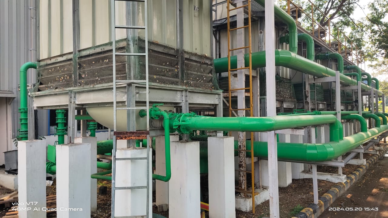
Chilled Water Pipe: How to Enhance HVAC Systems
In the modern world of construction and industrial processes, the proper functioning of heating, ventilation and air conditioning (HVAC) systems is critical to maintaining comfort, productivity and environmental sustainability. The…

- Blog , Clean Rooms , HVAC
- July 4, 2024
- 19 views
The Ultimate Guide to ISO Class 5 Cleanrooms
Explore the significance of ISO Class 5 cleanrooms in industries like biotechnology, semiconductor manufacturing, and medical engineering. Learn about contamination control, air purity standards, and certification requirements. The Ultimate Guide…

- Blog , HVAC
- July 3, 2024
- 18 views
AC Health Problems: The Hidden Risks of Chronic Air Conditioning
Air conditioning makes life more comfortable in hot climates. However, staying prolonged time may cause AC Health Problems in that environment and that to too long can have its drawbacks.…

- Blog , HVAC
- July 2, 2024
- 18 views
Kitchen Exhaust System: How to Design an Efficient HVAC Solution
Kitchen exhaust system play a vital role in maintaining air quality, safety and comfort in commercial and residential spaces. In the HVAC realm, these systems are essential components that cater…
- Blog , Clean Rooms , Data Centers , HVAC , Petrochemicals
- July 1, 2024
- 25 views
Vibration Isolation: How to Optimize HVAC Performance
This article on vibration isolation covers the supply, delivery, installation, and testing of noise and vibration control equipment used to isolate various mechanical devices in HVAC systems. The purpose of…
- Blog , Clean Rooms , Data Centers , HVAC , Petrochemicals
- June 30, 2024
- 24 views
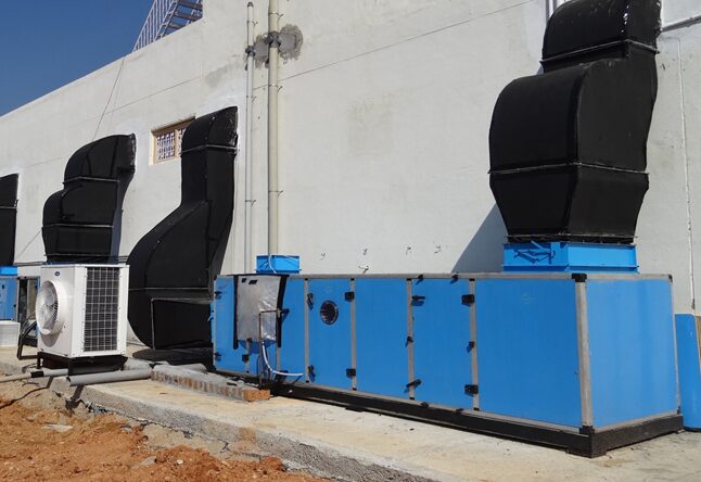
Air Handling Unit: Key and Best Practices of Technical Submittals
The packaged air handling unit (AHU) shall be factory assembled units in factory fabricated casings. Each unit shall be complete with aerofoil centrifugal blowers, motors, drives and guards, cooling coil…