Semiconductor Cleanroom Zoning: Best Practices of contamination control

Semiconductor Cleanroom Zoning layout in a semiconductor manufacturing facility to control contamination.

Semiconductor cleanroom zoning represents the backbone of contamination control in modern chip manufacturing facilities. This systematic approach to space planning ensures that different manufacturing processes operate within their required cleanliness levels while preventing cross-contamination between zones. The concept extends far beyond simple room separation, incorporating sophisticated airflow management, pressure differentials, and material flow control mechanisms that collectively maintain the sterile environment essential for semiconductor production.

Understanding the Critical Role of Semiconductor Cleanroom Zoning

The importance of proper zoning becomes evident when considering that a single particle measuring just 0.1 micrometers can destroy an entire semiconductor wafer worth thousands of dollars. Indian semiconductor facilities, particularly those emerging under government initiatives like the Production Linked Incentive scheme, must implement robust zoning strategies to compete globally. These facilities typically handle everything from basic assembly operations to advanced wafer fabrication, each requiring distinct contamination control approaches that reflect international standards while adapting to local operational conditions.

Effective zoning strategies directly impact production yield, operational efficiency, and compliance with international standards such as ISO 14644-1 and various semiconductor industry specifications. The complexity increases when facilities must accommodate multiple product lines, different cleanliness requirements, and varying process technologies within a single building envelope. Understanding these fundamentals forms the foundation for developing comprehensive contamination control strategies.

Enjoying this content? Get expert HVAC updates on our Telegram Channel.

Wafer Fab Layout Optimization Through Strategic Zone Planning

Wafer fab layout optimization demands careful consideration of process flow, equipment placement, and personnel movement patterns to minimize contamination risks. The traditional approach involves creating a linear flow from raw wafer input through various processing steps to final testing and packaging. However, modern facilities often require more complex layouts that accommodate multiple process lines, shared utilities, and flexible manufacturing capabilities while maintaining strict contamination control.

The optimization process begins with mapping critical process steps and identifying contamination-sensitive operations. Photolithography areas typically require the highest cleanliness levels, often ISO Class 1 or Class 10, while mechanical assembly operations might function adequately in Class 1000 or Class 10000 environments. This hierarchy drives the overall facility layout, with the cleanest areas positioned at the facility core and progressively less critical zones arranged in concentric rings around this central clean zone.

Modern Indian semiconductor facilities increasingly adopt the ballroom concept, where large open cleanroom spaces house multiple process tools with flexible reconfiguration capabilities. This approach offers significant advantages in terms of airflow management, equipment access, and future expansion possibilities. The ballroom layout typically features a raised floor system for utilities distribution and a sophisticated ceiling-mounted air handling system that provides laminar airflow across the entire space.

Personnel and material flow patterns significantly influence layout optimization decisions. Successful designs incorporate separate pathways for people and materials, with dedicated airlocks, gowning areas, and decontamination stations positioned strategically throughout the facility. The goal involves minimizing travel distances while ensuring that all movements follow contamination control protocols. Advanced facilities implement automated material handling systems that further reduce human presence in the most critical zones.

Chip Manufacturing Area Segregation Principles

Chip manufacturing area segregation operates on the fundamental principle that different manufacturing processes generate varying types and levels of contamination. Wet chemical processes, plasma etching, ion implantation, and photolithography each present unique challenges that require specific containment and isolation strategies. Effective segregation ensures that contamination from one process does not compromise the cleanliness requirements of adjacent operations.

Chemical segregation represents one of the most critical aspects of area planning in semiconductor facilities. Wet benches handling hydrofluoric acid require specialized exhaust systems and corrosion-resistant materials, while organic solvent processes demand explosion-proof electrical systems and appropriate fire suppression measures. These chemical-specific requirements often drive the decision to create dedicated zones with their own air handling systems, preventing cross-contamination between incompatible processes.

Particle generation characteristics also influence segregation decisions. Mechanical processes such as wafer dicing, grinding, and packaging operations generate significantly more particles than chemical vapor deposition or photolithography processes. Facilities typically locate high-particle-generation processes in separate zones with enhanced air filtration and higher air change rates to contain contamination at its source.

Temperature and humidity requirements further complicate segregation planning. Photolithography processes often require precise temperature control within ±0.1°C, while furnace operations might tolerate broader temperature ranges. Humidity sensitivity varies dramatically between processes, with some requiring less than 1% relative humidity while others function adequately at standard cleanroom conditions of 45±5% RH. These environmental requirements often necessitate separate air handling systems for different zones.

Cleanroom Classification Zones and Compliance Requirements

Cleanroom classification zones must align with specific industry standards and product requirements while providing practical operational flexibility. The ISO 14644-1 standard provides the international framework for cleanroom classification, defining particle concentration limits for different cleanliness classes. Indian semiconductor facilities typically implement multiple classification zones within a single facility, ranging from ISO Class 1 for critical photolithography areas to ISO Class 8 for packaging and assembly operations.

The classification system considers both particle size and concentration, with measurements typically conducted using laser particle counters capable of detecting particles as small as 0.1 micrometers. Class 1 cleanrooms permit no more than 10 particles per cubic meter of 0.1-micrometer size, while Class 100 allows up to 3,520 particles of the same size per cubic meter. These stringent requirements demand sophisticated air filtration systems, typically employing HEPA or ULPA filters with 99.999% efficiency ratings.

Monitoring and verification requirements add another layer of complexity to classification zone management. Facilities must conduct regular particle counts, airflow measurements, and filter integrity tests to maintain certification. Indian facilities often face additional challenges related to external environmental conditions, including higher dust levels and seasonal variations that can impact cleanroom performance. Successful operations implement continuous monitoring systems that provide real-time data on particle levels, allowing for immediate corrective actions when deviations occur.

The transition zones between different classification areas require careful design attention to prevent contamination migration. These areas typically incorporate air locks, pressure cascades, and specialized air handling systems that maintain appropriate pressure differentials while allowing personnel and material movement. The pressure differential between adjacent zones should typically maintain at least 2.5 Pascals, with higher differentials used when significant cleanliness differences exist.

Fab Facility Space Planning for Optimal Contamination Control

Fab facility space planning integrates multiple engineering disciplines to create environments that support both current operations and future expansion needs. The planning process must consider structural requirements, utility distribution, equipment access, emergency egress, and contamination control measures within a cohesive design framework. Modern facilities typically allocate 60-70% of total floor area to production spaces, with the remainder dedicated to support functions including mechanical rooms, offices, and material storage areas.

The vertical organization of fab facilities significantly impacts contamination control effectiveness. Most facilities employ a three-level design with mechanical equipment located on the top floor, cleanroom production areas on the middle level, and utility distribution through a raised floor system at the bottom level. This arrangement facilitates gravity-fed exhaust systems, simplified utility routing, and effective separation of clean and potentially contaminated zones.

Utility distribution planning requires careful coordination to minimize contamination risks while providing necessary services to all areas. Chemical distribution systems typically utilize dedicated corridors or interstitial spaces to isolate potentially hazardous materials from production areas. Electrical systems must comply with explosion-proof requirements in certain zones while providing the clean, stable power required for sensitive semiconductor equipment.

Future flexibility considerations increasingly influence space planning decisions as semiconductor technology continues evolving rapidly. Facilities must accommodate equipment changes, process modifications, and capacity expansions without compromising contamination control integrity. This requirement often drives decisions toward larger open spaces with flexible utility connections rather than fixed, process-specific room layouts.

Advanced Airflow Management Systems in Zoned Environments

Advanced airflow management systems form the technical foundation of effective cleanroom zoning, providing the means to maintain required particle levels while accommodating complex facility layouts. These systems must deliver appropriate air volumes, maintain pressure differentials, provide uniform air distribution, and minimize energy consumption across multiple zones with varying requirements. Modern facilities typically employ computer-based airflow simulation during design phases to optimize system performance and identify potential problem areas.

Laminar airflow systems represent the gold standard for critical semiconductor processes, providing unidirectional airflow that sweeps particles away from sensitive areas. These systems typically operate at velocities between 0.3 and 0.5 meters per second, creating a laminar boundary layer that prevents turbulent mixing and particle recirculation. The implementation requires precision-engineered air distribution systems with HEPA or ULPA filtration, often consuming 30-40% of total facility energy.

Mixed airflow systems offer energy advantages in less critical areas while maintaining adequate contamination control. These systems combine high-efficiency filtration with strategic air distribution to achieve required particle levels at lower energy costs. The key involves understanding particle generation patterns and designing airflow systems that capture contamination at its source before it can spread throughout the space.

Pressure cascade management becomes critical when multiple zones with different cleanliness requirements connect within a single facility. The system must maintain appropriate pressure differentials across all boundaries while accommodating door openings, equipment installations, and normal operational activities. Advanced facilities implement automated pressure control systems that adjust airflow rates in real-time to maintain required differentials despite changing conditions.

Contamination Source Identification and Control Strategies

Contamination source identification requires systematic analysis of all potential particle and chemical sources within semiconductor facilities. Human activities typically represent the largest contamination source, with personnel generating particles through skin shedding, clothing fibers, and respiratory emissions. Equipment operations contribute mechanical particles, chemical residues, and electromagnetic interference that can impact sensitive processes. External sources including outdoor air, construction activities, and utility systems add additional contamination challenges.

Personnel contamination control strategies encompass comprehensive gowning procedures, training programs, and behavioral modifications designed to minimize particle generation. Modern facilities implement multi-stage gowning sequences with air showers, sticky mats, and ionization systems that remove particles and static charges before personnel enter critical areas. The effectiveness depends heavily on employee training and adherence to established procedures, making ongoing education programs essential for maintaining contamination control standards.

Equipment-related contamination control focuses on both source elimination and containment strategies. Preventive maintenance programs help minimize particle generation from mechanical wear, while specialized enclosures contain contamination from high-particle-generation processes. Advanced facilities implement real-time particle monitoring systems that automatically adjust air filtration rates when equipment-generated contamination exceeds predetermined thresholds.

Chemical contamination presents unique challenges requiring specialized detection and control strategies. Outgassing from construction materials, cleaning solvents, and process chemicals can create molecular contamination that interferes with semiconductor processes even at extremely low concentrations. Facilities typically implement material selection programs, bake-out procedures, and specialized filtration systems designed to remove molecular contaminants from the cleanroom environment.

Environmental Control Integration Across Multiple Zones

Environmental control integration demands sophisticated coordination between temperature, humidity, pressure, and air quality management systems across multiple zones with varying requirements. The complexity increases when facilities must accommodate incompatible environmental conditions within adjacent spaces while maintaining energy efficiency and operational flexibility. Modern systems typically employ computer-based control strategies that optimize performance across all zones simultaneously rather than treating each area independently.

Temperature control strategies must address both sensible and latent heat loads while maintaining the precision required for semiconductor processes. Critical photolithography areas often require temperature stability within ±0.1°C, while general manufacturing areas might tolerate ±1°C variations. The challenge involves designing systems that provide required precision in critical areas without overconditioning less sensitive zones, which would waste energy and create operational inefficiencies.

Humidity control becomes particularly challenging in facilities with multiple zones requiring different moisture levels. Photolithography processes typically require very low humidity levels to prevent resist adhesion problems, while some chemical processes function better at moderate humidity levels that reduce static electricity generation. The solution often involves dedicated air handling systems for each zone with different humidity requirements, coupled with sophisticated moisture management strategies.

Integration challenges extend beyond basic environmental parameters to include air quality management, pressure control, and emergency response capabilities. Systems must coordinate responses to equipment failures, power outages, and other emergency conditions while maintaining contamination control integrity. Advanced facilities implement redundant systems and fail-safe operating modes that ensure critical areas remain protected even during equipment failures or maintenance activities.

Technology Integration for Smart Cleanroom Operations

Technology integration transforms traditional cleanroom operations through automation, real-time monitoring, and predictive maintenance capabilities that enhance contamination control effectiveness while reducing operational costs. Modern facilities typically implement integrated building management systems that coordinate HVAC operations, particle monitoring, access control, and emergency response functions through centralized control platforms. These systems provide operators with comprehensive facility status information and automated responses to changing conditions.

Sensor networks enable continuous monitoring of critical parameters including particle levels, temperature, humidity, pressure differentials, and chemical concentrations throughout the facility. Advanced systems employ wireless sensor networks that eliminate potential contamination sources associated with traditional wiring while providing flexible monitoring capabilities that can adapt to changing facility layouts. The data collected supports both real-time operational decisions and long-term performance optimization strategies.

Artificial intelligence applications increasingly support cleanroom operations through predictive maintenance programs, energy optimization algorithms, and contamination source identification systems. Machine learning algorithms analyze historical performance data to identify patterns that predict equipment failures, optimize filter replacement schedules, and recommend operational adjustments that improve contamination control effectiveness. These capabilities become particularly valuable in large facilities with complex interconnected systems.

Digital twin technology represents the latest advancement in cleanroom management, creating virtual facility models that support operational optimization, staff training, and scenario planning activities. These models incorporate real-time sensor data, equipment performance information, and environmental conditions to provide accurate representations of facility operations. Operators can use digital twins to test operational changes, train personnel, and optimize system performance without impacting actual production operations.

Energy Efficiency Considerations in Multi-Zone Design

Energy efficiency considerations significantly impact the economic viability of semiconductor cleanroom operations, with HVAC systems typically consuming 40-60% of total facility energy. Multi-zone designs offer opportunities for optimization through load matching, equipment right-sizing, and operational scheduling strategies that reduce energy consumption while maintaining required environmental conditions. The key involves understanding the relationship between contamination control requirements and energy consumption to identify optimization opportunities.

Heat recovery systems provide significant energy savings opportunities in facilities with simultaneous heating and cooling requirements. Many semiconductor processes generate substantial heat loads that must be removed from cleanroom areas, while other areas require heating during certain operational periods. Heat recovery systems capture waste heat from exhaust airstreams and use it to condition incoming fresh air, reducing both heating and cooling energy requirements.

Variable air volume systems enable energy optimization by adjusting airflow rates based on actual contamination control requirements rather than maintaining constant maximum flow rates. These systems typically incorporate real-time particle monitoring that automatically adjusts air change rates when contamination levels change. During periods of reduced activity, such as overnight or weekend operations, airflow rates can be reduced significantly while maintaining required cleanliness levels.

Equipment optimization strategies focus on improving the efficiency of individual system components including fans, pumps, chillers, and air handling units. Modern facilities typically employ high-efficiency equipment with variable speed drives that adjust operating parameters based on actual load requirements. Regular maintenance programs ensure equipment operates at peak efficiency, while equipment replacement programs systematically upgrade older, less efficient components.

Regulatory Compliance and Industry Standards

Regulatory compliance requirements significantly influence cleanroom zoning decisions, with facilities must meeting various national and international standards depending on their products and markets. Indian semiconductor facilities typically must comply with BIS standards, ISHRAE guidelines, international ISO standards, and specific customer requirements that may impose additional restrictions. The complexity increases when facilities serve multiple markets with different regulatory requirements.

ISO 14644-1 provides the primary international framework for cleanroom classification and testing procedures. This standard defines particle concentration limits for different cleanliness classes while specifying testing methods, monitoring frequencies, and certification requirements. Facilities must demonstrate compliance through regular testing programs that document particle levels, airflow rates, and filter performance across all classified areas.

ASHRAE standards provide guidance on HVAC system design, operation, and maintenance practices that support cleanroom applications. These standards address air filtration requirements, energy efficiency considerations, and indoor air quality management strategies that complement ISO cleanroom standards. The integration of multiple standards requires careful coordination to ensure all requirements are met without creating conflicting operational constraints.

Industry-specific standards add another layer of complexity, with semiconductor manufacturers often imposing requirements that exceed general cleanroom standards. These specifications typically address specific contamination concerns related to particular manufacturing processes, materials compatibility requirements, and quality assurance procedures that support high-yield production operations. Facilities serving multiple customers may need to accommodate different standards simultaneously within the same building.

Future Trends and Emerging Technologies

Future trends in semiconductor cleanroom zoning reflect ongoing advances in manufacturing technology, environmental control systems, and automation capabilities that promise to improve contamination control effectiveness while reducing operational costs. The industry continues moving toward smaller feature sizes and more complex manufacturing processes that demand increasingly sophisticated contamination control strategies. These trends drive innovations in facility design, equipment technology, and operational procedures.

Nanotechnology applications are emerging in air filtration systems, offering improved particle removal efficiency and lower pressure drops compared to traditional HEPA and ULPA filters. These advanced filtration media employ nanofiber technology that creates smaller pore sizes while maintaining high airflow rates. The technology promises significant energy savings while providing superior contamination control performance.

Advanced monitoring technologies including real-time molecular contamination detection, automated particle sizing, and wireless sensor networks provide unprecedented visibility into cleanroom performance. These systems enable proactive contamination control strategies that identify and address problems before they impact production operations. The integration with artificial intelligence algorithms supports predictive maintenance programs and operational optimization strategies that improve overall facility performance.

Sustainable design principles increasingly influence cleanroom development, with facilities incorporating renewable energy systems, water recycling programs, and waste minimization strategies that reduce environmental impact while maintaining required performance levels. These approaches align with corporate sustainability goals while potentially reducing operational costs through resource conservation and efficiency improvements.

Frequently Asked Questions

How to control contamination in a clean room?

Contamination control in cleanrooms requires a comprehensive approach combining advanced air filtration, positive pressure maintenance, strict personnel protocols, and regular monitoring. The primary strategy involves creating laminar airflow patterns that continuously remove particles while preventing external contamination entry through pressure cascades and airlocks.

What does class 100 and class 1000 clean room mean?

Class 100 cleanrooms allow maximum 100 particles of 0.5 micrometers per cubic foot, equivalent to ISO Class 5. Class 1000 permits up to 1000 particles of the same size, corresponding to ISO Class 6. These classifications define the maximum allowable particle concentrations for different manufacturing processes.

What are the clean room standards for semiconductors?

Semiconductor cleanroom standards primarily follow ISO 14644-1 for classification, with specific areas requiring ISO Class 1-5 depending on process sensitivity. Additional standards include SEMI specifications for equipment, ASHRAE guidelines for HVAC systems, and industry-specific requirements for molecular contamination control and electrostatic discharge protection.

How does a cleanroom primarily prevent contamination?

Cleanrooms prevent contamination through engineered airflow systems that create positive pressure environments with continuous air filtration. HEPA or ULPA filters remove particles while laminar airflow patterns sweep contaminants away from sensitive areas. Personnel protocols and material control procedures minimize contamination introduction.

What is the clean room market for semiconductors?

The global semiconductor cleanroom market is experiencing rapid growth, particularly in Asia-Pacific regions including India. Market expansion is driven by increasing semiconductor demand, advanced manufacturing technologies, and government initiatives supporting domestic chip production. The market encompasses construction, equipment, and ongoing operational services.

What are the key factors in cleanroom zone design?

Key factors include process compatibility, contamination sensitivity levels, personnel and material flow patterns, utility requirements, regulatory compliance needs, and future flexibility requirements. Successful designs integrate these factors while optimizing energy efficiency and operational costs throughout the facility lifecycle.

Disclaimer

The content here is intended solely for educational and informational purposes. All case studies, examples, and hypothetical scenarios are illustrative in nature and do not refer to, endorse, or represent any actual company, organization, or product. Any similarity to real-world entities or events is purely coincidental. Readers are encouraged to verify any technical details or operational recommendations with additional, independent research prior to implementation. The author and publisher assume no responsibility or liability for any errors, omissions, or outcomes resulting from the use of this material.

About the Author

Mr. Om Prakash, with over 18 years of hands-on experience in the HVAC industry, brings unmatched expertise in cleanroom, semiconductor, pharmaceutical, data center, commercial, and industrial HVAC systems. As the founder of HVAC Technocrat, he specializes in customized HVAC design, energy efficiency audits, retrofit planning, and turnkey consultancy services across India. He simplifies complex HVAC concepts and shares real-world insights to support professionals, facility managers, and decision-makers. For enquiries or project support, call or WhatsApp at +91 9908091942, email hvactechnocrats@gmail.com, or visit www.hvactechnocrat.com. Also, follow his LinkedIn profile.

How to Calculate Semiconductor ACPH and Airflow

Advanced semiconductor ACPH clean room with HVAC system showcasing ACH and airflow management

Semiconductor clean rooms demand precise environmental control. In these facilities, engineers design HVAC systems that calculate air changes per hour ACPH and manage airflow requirements with extreme accuracy. Semiconductor clean room performance depends on proper ACPH calculations, as even small errors may affect wafer quality and chip performance. In semiconductor manufacturing, ensuring that HEPA filtration, temperature regulation, and humidity control work harmoniously is critical. This article explains how to calculate semiconductor ACPH, determine proper airflow, and implement effective HVAC designs for semiconductor clean rooms.

Understanding the Concept of Semiconductor ACPH in Clean Rooms

Air changes per hour (ACPH) represent the number of times a room’s air volume is completely exchanged in one hour. In semiconductor clean rooms, engineers calculate ACH by dividing the total volume of air supplied by the room volume. Practically, designers measure the airflow in cubic meters per hour and divide it by the clean room’s volume in cubic meters. ACH plays a key role in controlling airborne contaminants and ensuring the clean room maintains its designated classification. For example, excessive airflow may lower energy efficiency, whereas insufficient airflow can lead to contamination. Therefore, the balance achieved through accurate ACH calculations supports continuous production stability and robust contamination control.

Furthermore, semiconductor clean room ACH calculations help designers determine the optimum layout of fan filter units (FFUs) and ductwork. An optimized ACH ensures that ultra-clean air flows uniformly over sensitive equipment. Manufacturers also use computer-based airflow simulations to verify that calculated ACH meets real-world performance. Industry standards such as ISO 14644-1 and guidelines from ASHRAE and ISHRAE ensure that semiconductor facilities conform to regulatory requirements. Properly calculated ACH reduces the probability of airborne contaminants interfering with chip manufacturing processes.

Calculating Semiconductor ACPH and Airflow Requirements in Clean Rooms

Engineers determine airflow by considering clean room dimensions, occupancy, equipment heat loads, and contamination risks. Designers calculate required air volume by multiplying air changes per hour (ACH) with the room’s volume. Typically, clean room airflow is measured in cubic meters per hour (m³/h) or cubic feet per minute (CFM). For semiconductor applications, airflow must maintain a unidirectional (laminar) pattern that pushes contaminants away from production areas.

Additionally, advanced HVAC systems monitor airflow rates continuously. They adjust fan speeds and duct configurations, thereby ensuring that the volume of air delivered meets exact process requirements. Semiconductor clean room designs include sensors that track air velocity and supply volumes, providing instant feedback if deviations occur. This proactive approach helps minimize downtime and ensures that even minor fluctuations in airflow do not compromise the manufacturing environment.

Key HVAC Parameters and Their Importance in Semiconductor Clean Rooms

Several HVAC parameters influence semiconductor clean room performance. Besides ACH, engineers carefully control temperature, humidity, and positive pressure. Temperature stability within a range of 20°C to 22°C (±0.1°C) prevents thermal expansion or contraction that may cause defects during photolithography. Humidity control (typically maintained between 40% and 60% relative humidity) reduces the risk of electrostatic discharge (ESD) and condensation issues. Positive pressure in the cleanroom prevents unfiltered air from entering from surrounding areas.

Moreover, designers plan the placement of supply diffusers and return vents to achieve uniform airflow distribution. Proper pressure gradients and airflow zoning guarantee that contaminants do not settle on critical wafers. Integrating smart controls into HVAC systems further refines the operation by automatically adjusting to changes in environmental conditions. These measures not only protect semiconductor products but can also lead to energy savings and reduced operational costs.

Methods and Formulas for Calculating Semiconductor ACPH Clean Rooms

Calculating ACH follows a simple formula:

ACH = (Airflow Rate ÷ Room Volume)

For example, if a clean room has a volume of 1,000 m³, and the HVAC system delivers 20,000 m³/h, then:

ACPH = 20,000 ÷ 1,000 = 20 air changes per hour

Q = Volume x ACPH / 60; where Q in cubic feet per min, Volume in cubit feet, ACPH in number

Additionally, engineers often convert airflow from CFM to m³/h (1 CFM ≈ 1.7 m³/h) and consider these conversions during design calculations. Furthermore, designers factor in the efficiency of ductwork and filter media, which might lower the effective airflow delivered.

Case studies reveal that semiconductor facilities in India have achieved optimized ACH by carefully balancing airflow with energy considerations. In one anonymized case study, a semiconductor plant improved its yield by 15% after recalculating ACH to better match clean room dimensions and process requirements. This demonstrates that precise measurement and control of ACH directly impact production efficiency.

Airflow Measurement Techniques and Instrumentation

Accurate airflow measurement is pivotal for proper ACH calculations. Engineers use an array of instruments, such as anemometers, airflow capture hoods, and manometers. These devices provide real-time measurements of air velocity and pressure. For instance, digital anemometers measure the speed of the air flowing out of fan filter units, which is then used in the ACH formula.

Moreover, sensors in the HVAC system alert operators if airflow falls below required levels. Continuous monitoring not only helps maintain clean room classification but also supports energy-efficient operation. A semiconductor clean room with misaligned airflow may experience increased energy consumption or, worse, contamination issues. Utilizing modern instrumentation thus ensures that semiconductor HVAC systems perform reliably over time.

Optimizing HVAC System Design for Semiconductor Clean Rooms

Optimal HVAC system design for semiconductor clean rooms includes several aspects:

  • Precise Calculations: Use accurate measurements for ACH and total airflow, ensuring uniform distribution.
  • Efficient Filtration: Integrate HEPA filters with a high removal efficiency (99.97% at 0.3 microns), which maintain low particle counts.
  • Smart Controls: Implement sensor networks and building automation systems (BAS) that adjust air supply dynamically.
  • Energy Efficiency: Design systems that balance high airflow with low energy consumption by using variable frequency drives (VFDs) and heat recovery measures.

Designers also use computer-based simulations to model airflow trajectories. This method, known as CFD (computer-based airflow simulations), helps predict how air moves throughout the clean room. Internal links to detailed guides on Clean Room Design and Construction provide more insights on this topic. Such simulations contribute to achieving the optimal balance between contamination control and energy efficiency.

Impact of Room Layout and Geometry on Airflow Requirements

Room layout and geometry significantly affect airflow performance. Semiconductor clean rooms use a combination of modular panels, raised floors, and dedicated gowning zones to optimize airflow. The placement of equipment, workstations, and staff affects how clean air flows throughout the room. Engineers design layouts that support unidirectional airflow, which clears out contaminants quickly and prevents stagnation.

For example, facilities in semiconductor manufacturing incorporate zigzag or serpentine airflow patterns to avoid dead zones. Additionally, strategic placement of diffusers ensures that air reaches every part of the clean room. These design choices not only improve the effectiveness of HVAC systems but also enhance energy efficiency by minimizing the need for excessive airflow.

Challenges in Calculating Ach and Airflow in Semiconductor Clean Rooms

Several challenges arise when calculating ACH and airflow in semiconductor clean rooms. First, the complex geometry of high-density equipment and varying occupancy levels can lead to uneven air distribution. Second, filters and ducts may introduce pressure drops, which affect the actual airflow rate delivered to the clean room space. Third, the dynamic nature of manufacturing processes means that airflow requirements may change over time.

Engineers must address these issues by performing regular audits, conducting CFD analyses, and recalibrating sensors. In one case study from India, recalibration of airflow systems led to a 10% energy savings and a more uniform ACH across production areas. By overcoming these challenges, semiconductor facilities improve both product yield and operational cost-effectiveness.

Future Trends: AI, IoT, and Smart Monitoring in ACH Calculations

Emerging technologies such as artificial intelligence (AI) and the Internet of Things (IoT) are revolutionizing HVAC system optimization. Modern semiconductor clean rooms now utilize smart sensors that continuously feed data about temperature, humidity, and airflow into centralized control systems. AI algorithms analyze these data streams in real time, predicting maintenance needs and optimizing air delivery for the calculated ACH.

For example, early AI-driven predictive analytics have helped reduce downtime by alerting facility operators to potential system inefficiencies before they cause contamination events. IoT connectivity further supports energy-efficient operations by automatically adjusting fan speeds and air distribution based on process demands. These innovations promise greater precision in ACH calculations and a more sustainable operation.

Calculating ACH: Practical Case Studies and Industry Examples

Several semiconductor clean room facilities have successfully optimized their HVAC systems by closely monitoring ACH. One semiconductor plant in Hyderabad recalculated its airflow requirements by installing advanced sensors and integrating a smart BAS. This resulted in a 15% increase in yield and a 10% decrease in energy costs. Another example from a facility in South Korea demonstrated that recalculating ACH to account for recirculating air improved contamination control and extended filter lifespan.

These case studies underscore how crucial accurate ACH calculations are in real-world scenarios. They offer practical insights into how minor adjustments in airflow rates can yield significant benefits in terms of performance and cost savings.

Strategies for Enhancing Energy Efficiency and Airflow Control

Semiconductor clean room HVAC systems must balance high performance with energy efficiency. Several strategies help achieve this balance:

  • Variable Frequency Drives (VFDs): Adjust fan speeds automatically based on real-time process requirements.
  • Heat Recovery Systems: Reuse waste heat from the clean room to pre-condition incoming air.
  • Regular Maintenance and Calibration: Maintain sensor accuracy and system performance to ensure that calculated ACH remains reliable over time.
  • Design Optimization: Use CFD simulations to optimize duct routes and diffusers in relation to clean room geometry.

Furthermore, implementing such strategies not only guarantees contamination control but also reduces the operating costs significantly. Manufacturers across the globe, including those in India, have noted improvements in overall efficiency after adopting these measures.

Integrating Standards and Regulatory Guidelines in ACH Calculations

Compliance with established standards safeguards semiconductor clean rooms from performance lapses. HVAC systems in such facilities must adhere to ISO 14644-1, which details classification and airflow criteria, as well as SEMI standards that illustrate industry-specific requirements. Designers also refer to guidelines from ASHRAE and ISHRAE to ensure that their calculations follow best practices.

Regulatory compliance includes detailed documentation in cleanroom PDFs and continuous monitoring protocols. These practices help maintain a stable environment that meets stringent criteria and supports high-yield semiconductor production.

Future of Semiconductor ACH Calculations: Trends and Innovations

The next generation of semiconductor HVAC systems will integrate even more advanced predictive maintenance and AI-powered monitoring capabilities. Increased reliance on data analytics and IoT devices will allow for real-time adjustments to ACH, ensuring that the clean room environment remains consistent with process demands. In addition, emerging trends toward carbon-neutral retrofits and sustainable HVAC technology further drive innovation in this field.

As semiconductor manufacturing evolves, these technological advancements will greatly impact how engineers calculate and control ACH. Facilities that adopt these innovations enjoy not only cleaner environments but also reduced energy consumption and enhanced operational reliability.

Internal Linking for Expanded Insights

For readers seeking further details on related topics, consider exploring our additional articles:

These internal links provide valuable, supplementary information related to HVAC design principles and energy-efficient systems.

FAQs

What is the significance of calculating semiconductor ACPH in clean rooms?

Calculating ACH is crucial because it defines how often the entire volume of air in a clean room is replaced. A properly calculated ACH ensures that contaminants are continuously removed, maintaining strict environmental conditions necessary for semiconductor manufacturing.

How is airflow measured in semiconductor clean room HVAC systems?

Engineers use instruments like anemometers and airflow capture hoods to measure air velocity and volume. They convert these measurements into cubic meters per hour and divide by the clean room’s volume to determine ACH.

What factors influence the appropriate airflow requirements for a semiconductor clean room?

Factors include the room volume, required cleanliness class (based on ISO 14644-1), heat loads from equipment, occupancy, and the design of fan filter units. Designers also consider pressure differentials and laminar airflow patterns.

How do smart controls enhance ACH performance in clean rooms?

Smart controls use IoT sensors and AI to monitor temperature, humidity, and airflow in real time. They automatically adjust fan speeds and air distribution to maintain steady ACH and ideal conditions.

What challenges do engineers face when calculating ACH?

Challenges include addressing complex room geometries, compensating for pressure drops in ducts and filters, and accommodating fluctuations in occupancy and equipment usage. Regular calibration and advanced simulations help overcome these challenges.

How do international standards and industry guidelines influence ACH calculations?

Standards such as ISO 14644-1 and guidelines from SEMI, ASHRAE, and ISHRAE provide benchmarks for allowable particle levels and environmental conditions. Compliance with these standards ensures that calculated ACH meets the strict demands of semiconductor fabrication.

Can ACH calculations adapt to changing production conditions?

Yes, with continuous monitoring and smart HVAC controls, ACH calculations can dynamically adjust to accommodate changes in production processes, occupancy, and equipment load, ensuring optimal performance at all times.

About the Author

Mr. Om Prakash, with over 18 years of hands-on experience in the HVAC industry, brings unmatched expertise in cleanroom, semiconductor, pharmaceutical, data center, commercial, and industrial HVAC systems. As the founder of HVAC Technocrat, he specializes in customized HVAC design, energy efficiency audits, retrofit planning, and turnkey consultancy services across India. He simplifies complex HVAC concepts and shares real-world insights to support professionals, facility managers, and decision-makers. For any enquiries or project support, call or WhatsApp at +91 9908091942, email hvactechnocrats@gmail.com, or visit www.hvactechnocrat.com. Also, follow his LinkedIn profile for more updates.

Disclaimer

The content here is intended solely for educational and informational purposes. All case studies, examples, and hypothetical scenarios are illustrative in nature and do not refer to, endorse, or represent any actual company, organization, or product. Any similarity to real-world entities or events is purely coincidental. Readers are encouraged to verify any technical details or operational recommendations with additional, independent research prior to implementation. The author and publisher assume no responsibility or liability for any errors, omissions, or outcomes resulting from the use of this material.

Semiconductor Clean Rooms: How to Design HVAC Systems

Semiconductor clean rooms technician checking HEPA filter integrity.

In semiconductor manufacturing, where nanoscale precision is non-negotiable, maintaining an ultra-clean environment is paramount. This is where semiconductor clean rooms come into play—controlled spaces engineered to eliminate airborne contaminants that could compromise wafer integrity and chip performance.

But what powers these pristine environments? The answer lies in highly specialized HVAC systems designed not for comfort, but for ultra-precise environmental control.

What Is the Concept of Clean Rooms?

A clean room is a controlled space where pollutants such as dust, microbes, aerosols, and chemical vapors are filtered out using advanced air purification systems. These rooms maintain strict limits on particulate matter, temperature, humidity, and pressure, ensuring that sensitive processes like photolithography and deposition can occur without interference.

Semiconductor fabrication, biotech research, and pharmaceutical production all rely on cleanrooms to ensure product yield and quality.

Clean Room Meaning and Containment

The core principle of a clean room is containment—either protecting the process from contamination (positive pressure) or protecting personnel from hazardous materials (negative pressure). In semiconductor clean rooms, the focus is on keeping the manufacturing area free from particles as small as 0.1 microns.

Containment is achieved through:

  • HEPA/ULPA filtration
  • Laminar airflow patterns
  • Pressure-controlled zones
  • Controlled entry protocols

What Are the Different Types of Cleanrooms?

Clean rooms are categorized based on airflow and application:

  • Turbulent Airflow Cleanrooms: Random air movement; suitable for ISO Class 7–9.
  • Laminar Airflow Cleanrooms: Unidirectional flow (vertical or horizontal); ideal for ISO Class 1–5.

Other types include:

  • Modular Cleanrooms: Quick-to-deploy structures with flexible layouts.
  • Softwall & Hardwall Cleanrooms: Based on material durability and permanence.

Each type serves specific industrial needs, with laminar airflow being the gold standard for semiconductor manufacturing.

What Is a Clean Room in GMP?

Under Good Manufacturing Practices (GMP), a clean room is defined as a classified area where microbial and particulate levels are controlled within defined limits. These standards are crucial in both pharmaceutical and semiconductor industries to meet regulatory compliance from bodies like the FDA, EMA, and CDSCO.

Semiconductor Clean Rooms Classification

Semiconductor clean rooms adhere to ISO 14644-1 classification, which defines allowable particle counts per cubic meter:

ISO ClassMax Particles ≥0.3 µm/m³
ISO 110
ISO 2100
ISO 31,000
ISO 410,000
ISO 5100,000

Most semiconductor fabrication lines require ISO Class 3 or 4, equivalent to older Class 10 or Class 100 standards under FS 209E.

What Are the Requirements for a Semiconductor Clean Rooms?

To maintain the required conditions for microchip production, semiconductor clean rooms must meet stringent requirements:

  • Air Changes per Hour (ACH): Typically between 300–600 ACH
  • Temperature Control: Maintained at 22°C ± 0.5°C
  • Relative Humidity (RH): Kept at 45% ± 5% RH
  • Pressure Gradient: Positive pressure maintained to prevent ingress of contaminants
  • Particle Count: <10 particles ≥0.3 µm/m³ for ISO Class 3
  • Vibration & Electrostatic Discharge (ESD) Control
  • Material Compatibility: Use of non-shedding, ESD-safe materials

These parameters ensure optimal conditions for wafer processing, lithography, and deposition.

What Is the Temperature of a Semiconductor Clean Rooms?

Maintaining precise thermal conditions is critical. The standard operating temperature is typically kept at 22°C ± 0.5°C. Even minor fluctuations can affect wafer expansion, lithography accuracy, and equipment performance.

Humidity is also tightly controlled to prevent static buildup and condensation issues that could damage sensitive components.

HVAC Systems for Semiconductor Clean Rooms

The HVAC system is the backbone of any semiconductor clean room. It ensures continuous delivery of filtered, temperature- and humidity-controlled air to maintain ISO-defined cleanliness levels.

Key Components of Cleanroom HVAC Systems:

  • Makeup Air Units (MAUs): Deliver treated outdoor air to replace exhausted indoor air.
  • Recirculating Air Units (RAUs): Maintain climate control and filtration without constant fresh air intake.
  • HEPA/ULPA Filters: Installed at terminal ends to capture submicron particles.
  • Variable Frequency Drives (VFDs): For energy-efficient fan control.
  • Control Systems: BMS/BAS for real-time monitoring and adjustments.

These systems operate continuously, often with redundant backups to avoid process interruptions.

Cleanroom HVAC Design PDF and Calculations

Designing HVAC systems for semiconductor clean rooms involves complex calculations:

  • Airflow Volume (CFM/LPM): Based on room size and ACH.
  • Heat Load Analysis: Equipment, lighting, and people contribute to internal loads.
  • Humidity Control: Latent vs sensible cooling load.
  • Filter Pressure Drop and Efficiency
  • Duct Sizing and Velocity Optimization

Comprehensive HVAC design PDFs often include schematics, psychrometric charts, and control sequences tailored to ISO and ASHRAE standards.

Many companies publish detailed cleanroom HVAC design guides and calculation templates, which serve as valuable references during facility planning.

Semiconductor Cleanroom Design

An effective semiconductor cleanroom integrates:

  • Zoned Layouts: Separating critical process zones from support areas.
  • Personnel & Material Flow Protocols: Minimizing contamination risk.
  • Modular Flexibility: Allowing future reconfiguration.
  • Integrated Monitoring Systems: Real-time data logging and alerts.

Design should comply with ASHRAE Standard 170 and ISO 14644-1 for global compliance.

Semiconductor Clean Rooms Jobs

With India’s growing semiconductor industry, job opportunities in cleanroom operations are expanding rapidly. Key roles include:

  • Cleanroom Technicians
  • Process Engineers
  • HVAC Maintenance Specialists
  • Facility Managers
  • QA/QC Inspectors

These professionals work in leading firms involved in chip manufacturing, packaging, and testing.

Semiconductor Clean Rooms Standards

Semiconductor clean rooms follow globally recognized standards:

  • ISO 14644-1 & 2: Classification and compliance testing.
  • ASHRAE Handbook – HVAC Applications: Provides standards and best practices for cleanroom HVAC system design.
  • Federal Standard 209E: Legacy reference for many facilities.
  • IS 15518:2004: Indian standard for cleanrooms.

Adherence to these ensures consistency in product yield, quality, and regulatory approval.

Conclusion

In semiconductor manufacturing, even the smallest particle can cause catastrophic failure. That’s why HVAC systems in clean rooms go far beyond basic heating and cooling—they are precision-engineered to maintain ultra-low contamination levels, stable thermal conditions, and continuous operation.

From ISO classifications to HVAC design principles, every detail plays a role in ensuring that the next generation of chips meets the highest standards of reliability and performance.

About the Author

Mr. Om Prakash is a seasoned HVAC expert with over 18 years of experience in cleanroom, pharmaceutical, semiconductor, and data center HVAC systems. As the founder of HVAC Technocrat, he offers end-to-end consultancy and customized solutions across India. He simplifies complex HVAC concepts to help professionals and facility managers make informed decisions.

Connect with him on LinkedIn or visit www.hvactechnocrat.com for expert guidance.

HVAC Consultant: How they Can Save You Money and Energy

HVAC consultant analyzing building energy performance on a blueprint layout.

In today’s competitive industrial and commercial landscape, optimizing HVAC systems isn’t just about comfort—it’s about cost savings, energy efficiency, and sustainability. Whether you manage a pharmaceutical cleanroom, a semiconductor facility, a data center, or a large commercial building, an experienced HVAC consultant can help you cut operational costs, enhance performance, and meet regulatory standards.

This article explores how an HVAC consultant add value, the key services they offer, and real-world examples of energy and cost savings that can transform your HVAC systems for maximum efficiency and sustainability.

Why Hire an HVAC Consultant?

HVAC systems account for 40-60% of a building’s energy consumption. However, poor design can lead to skyrocketing bills, while frequent breakdowns drive up maintenance costs. Additionally, non-compliance with energy codes may result in penalties. Moreover, Poor indoor air quality (IAQ) affecting health & productivity. For these reasons, professional intervention is critical.

    An HVAC consultant identifies inefficiencies, recommends upgrades, and ensures systems run at peak performance with minimal waste.

    Key Services Offered by an HVAC Consultant

    1. Value Engineering: Optimizing Costs Without Compromising Quality

    Instead of overspending on oversized equipment or unnecessary features, consultants perform value engineering—analyzing system requirements and suggesting cost-effective alternatives.

    ✅ Case Study: A Hyderabad-based IT park reduced HVAC installation costs by ₹58 lakhs after a consultant optimized chiller capacity, piping sizing and ductwork routing layout.

    2. Energy Audits: Pinpointing Waste & Recommending Solutions

    Energy audits assess how efficiently your HVAC system operates and identify:

    • Overcooling/overheating zones
    • Air leaks in ducts
    • Inefficient equipment (old chillers, pumps, fans)
    • Opportunities for heat recovery

    ✅ For Instance: A pharmaceutical plant in Bengaluru cut energy bills by 25% after an audit revealed excessive fan power usage—solved by switching to EC motors.

    3. Retrofit Design Analysis: Upgrading Old Systems for Better Efficiency

    Many facilities run on decades-old HVAC systems that guzzle energy. Consultants analyze:

    • Replacement vs. repair economics
    • New tech options (VRF, inverter chillers, smart controls)
    • ROI on energy-efficient retrofits

    ✅ In another Example: A commercial complex in Mumbai replaced its 20-year-old chillers with magnetic-bearing models, reducing energy consumption by 40%—payback in 33 months.

    4. Greenfield Projects: Designing Efficient HVAC from Scratch

    For new constructions (data centers, cleanrooms, industrial plants), consultants ensure:

    • Right-sizing equipment (avoiding over/under-capacity)
    • Sustainable design (solar-assisted cooling, efficient motors options)
    • Compliance with ASHRAE, ISHRAE, ECBC, and LEED standards

    ✅ Similarly: A semiconductor facility in Chennai saved ₹1.2 crore/year by integrating adiabatic cooling instead of traditional DX systems.

    5. Planning, Estimation & Tendering: Avoiding Costly Mistakes

    A poorly planned HVAC project can lead to budget overruns and delays. Consultants help with:

    • Accurate load calculations
    • Equipment selection (chillers, AHUs, pumps)
    • Bid evaluation & contractor selection

    ✅ Another Case Study: A hospital in Bangalore avoided ₹25 lakhs in rework after a consultant corrected incorrect duct sizing in initial plans.

    HVAC Sustainability & Energy Efficiency Solutions

    With rising electricity costs and stricter environmental regulations, businesses must adopt sustainable HVAC practices. Consultants recommend:

    • Heat recovery systems (waste heat reuse)
    • Mag-Lev bearing chillers
    • Solar-powered motors for AHUs and Fans
    • AI-driven predictive maintenance
    • Thermal energy storage
    • Building automation systems (BAS) for smart controls

    ✅ Case Study: A Hyderabad mall installed IoT-based HVAC controls, reducing energy use by 25% while maintaining optimal comfort.

    Why Choose Mr. Om Prakash – HVAC Consultant at www.hvactechnocrat.com?

    With 18+ years of expertiseMr. Om Prakash has helped pharmaceutical plants, data centers, semiconductor facilities, and commercial buildings across India and abroad optimize their HVAC systems for energy efficiency and cost savings.

    What Sets Him Apart?

    ✔ Deep Technical Knowledge – Specializes in cleanrooms, data centers, industrial HVAC, and green building compliance.
    ✔ Hands-On Experience – Successfully executed 100+ projects in design, audits, retrofits, and energy optimization.
    ✔ Cost-Saving Strategies – Expertise in value engineering to reduce capital and operational expenses.
    ✔ Sustainability Focus – Designs systems aligned with ECBC, LEED, ISHRAE and ASHRAE standards for long-term efficiency.

    Services Offered:

    🔹 HVAC Design & Planning for commercial buildings
    🔹 Energy Efficiency Audits
    🔹 Retrofit & Modernization Studies
    🔹 Cleanroom, Pharma and Semiconductor HVAC Solutions
    🔹 Data Center Cooling Optimization
    🔹 Tender Documentation & Bid Evaluation

    Real-World Impact:

    🏭 A Hyderabad pharma company saved ₹42 lakhs/year after Mr. Om Prakash redesigned their HVAC system’s capacity, airflow & filtration system.
    🏢 A commercial tower reduced HVAC energy use by 30% through AI-based load optimization.

    📞 For Expert HVAC Consulting in Hyderabad & Across India:
    📱 Call/WhatsApp: +91 9908091942
    📧 Email: hvactechnocrats@gmail.com
    🌐 Visit: www.hvactechnocrat.com

    FAQs

    1. How much can an HVAC consultant save me?

    Savings depend on system inefficiencies—typically 20-40% on energy bills and 10-30% on maintenance costs.

    2. Is hiring a HVAC consultant worth it for small businesses?

    Yes! Even small facilities can save lakhs annually with proper HVAC optimization.

    3. How long does an energy audit take?

    Usually 2-5 days, depending on facility size.

    4. Can HVAC consultant help with green building certifications?

    Absolutely! They ensure compliance with LEED, IGBC, and ECBC norms.

    5. What’s the ROI on HVAC retrofits?

    Most projects pay back in 2-4 years through energy savings.

    6. Do HVAC consultant handle contractor coordination?

    Yes, they oversee design, installation, and commissioning to avoid errors.

    Final Thoughts

    An HVAC consultant isn’t an expense—it’s an investment that pays off in lower bills, fewer breakdowns, and better compliance. Whether you need energy audits, retrofit designs, or greenfield project planningMr. Om Prakash at www.hvactechnocrat.com brings 18+ years of expertise to deliver cost-effective, sustainable HVAC solutions.

    📞 Contact today for a consultation!
    📱 +91 9908091942 | 📧 hvactechnocrats@gmail.com

    Disclosure: Some links may be affiliate-based, supporting our research at no extra cost to you. We maintain strict editorial independence.

    3D Printed Ductwork is the Next Big Thing in HVAC

    3D printed ductwork installation in a commercial building.

    3D Printed Ductwork is the Next Big Thing in HVAC

    The HVAC industry is on the brink of a quiet revolution, and it’s being shaped layer by layer—literally. 3D printed ductwork, once a niche concept, is now emerging as a game-changer for commercial, industrial, and even residential projects. By combining design flexibility, material efficiency, and faster installation, this technology addresses long-standing challenges in ductwork fabrication. From Mumbai’s high-rises to Berlin’s green buildings, engineers are leveraging additive manufacturing to create custom ducts that slash waste, reduce labor costs, and optimize airflow. This article explores how 3D printing is redefining ductwork, backed by global case studies, technical insights, and actionable strategies for HVAC professionals.

    The Limitations of Traditional Ductwork

    Conventional ductwork fabrication relies on sheet metal, fiberglass, or flexible ducts, which often involve time-consuming cutting, welding, and assembly. These methods struggle with complex geometries, leading to inefficient airflow, pressure drops, and energy losses. In India, where space constraints in urban buildings demand compact designs, rigid rectangular ducts dominate, but they rarely align perfectly with dynamic architectural layouts. A 2022 ASHRAE report noted that 25–30% of HVAC energy losses in commercial buildings stem from poorly designed or leaky duct systems.

    For example, a Chennai-based hospital retrofit faced delays when pre-fabricated ducts couldn’t navigate around existing electrical conduits. The team resorted to on-site modifications, increasing labor costs by 40%. Such inefficiencies underscore the importance of adopting a more intelligent strategy.

    How 3D Printing Works for Ductwork

    3D printing, or additive manufacturing, builds ducts layer by layer using materials like polymers, composites, or even metal alloys. Unlike traditional methods, it allows for:

    • Custom geometries: Spiral, oval, or branching ducts that minimize turbulence.
    • Integrated features: Built-in dampers, sensors, or insulation layers.
    • On-demand production: Print ducts onsite or in modular sections, reducing transport costs.

    A German engineering firm recently printed a fractal-inspired duct system for a Leipzig office tower. The design reduced airflow resistance by 22% compared to standard rectangular ducts, cutting energy use by 15%. Similarly, a pilot project in Pune used recycled PETG plastic to print lightweight ducts for a retail complex, achieving a 30% faster installation.

    Key Benefits of 3D Printed Duct

    1. Material Efficiency: Traditional methods waste up to 20% of sheet metal due to cutting errors. 3D printing uses only the material needed, aligning with India’s Zero Defect, Zero Effect (ZED) manufacturing goals.
    2. Labor Savings: A Mumbai commercial project cut ductwork labor hours by 50% by printing complex junctions onsite, avoiding manual assembly.
    3. Performance Optimization: Computational fluid dynamics (CFD) simulations can inform duct designs that traditional workshops can’t replicate. A Seoul data center used 3D-printed tapered ducts to balance airflow across server racks, eliminating hotspots.

    Case Study: Bengaluru’s Green Office Tower

    A LEED Platinum-certified office in Bengaluru adopted 3D printed ducts to meet tight sustainability targets. Key steps included:

    • Scanning the building’s structure with BIM (Building Information Modeling) to design ducts that fit around beams and pipes.
    • Printing ducts with recycled polycarbonate, reducing material costs by ₹8 lakh.
    • Integrating airflow sensors directly into duct walls for real-time monitoring.

    The result? A 25% reduction in HVAC energy use and a 3-month shorter construction timeline. The project adhered to India’s ECBC standards and received recognition under the IGBC Green New Building rating system.

    Challenges and Solutions

    While promising, 3D printed ductwork faces hurdles:

    • Material Limitations: Most polymers can’t withstand temperatures above 80°C. Solution: Metal 3D printing (e.g., aluminum alloys) for high-heat applications.
    • Regulatory Gaps: India’s National Building Code (NBC) lacks specific guidelines for 3D ducts. Solution: Collaborate with BIS to draft additive manufacturing standards, as seen in Singapore’s SS 674 certification.
    • Cost of Printers: Industrial 3D printers can cost ₹50 lakh–₹2 crore. Solution: Partner with local startups offering printing-as-a-service, like a Delhi-based firm charging ₹1,500 per kg of printed duct.

    Global Innovations Shaping the Future

    1. Self-Healing Materials: Dutch researchers are testing ducts embedded with microcapsules that seal minor leaks automatically.
    2. Solar-Absorbing Ducts: A Sydney project used carbon-fiber ducts that harness waste heat for water preheating, saving AU$12,000 annually.
    3. Hybrid Systems: In Japan, ducts are printed with grooves for modular insulation panels, simplifying retrofits.

    The Indian Context: Opportunities and Adaptations

    India’s HVAC market, projected to grow at 15% CAGR, is ripe for 3D disruption. Startups like 3D Housing (anonymized) are partnering with builders to print ducts for affordable housing projects. The Swachh Bharat Mission’s focus on sustainable construction further incentivizes waste-reducing technologies.

    For instance, a Surat school used 3D-printed PLA (polylactic acid) ducts in its new science wing. The biodegradable material, priced 20% lower than GI sheet, withstood Gujarat’s humidity and reduced installation time by 60%.

    Cost Analysis: 3D vs. Traditional Ductwork

    FactorTraditional Ducts3D Printed Ducts
    Material Waste15–20%<5%
    Labor Costs (per sq. ft.)₹180–₹250₹90–₹150
    Lead Time4–6 weeks1–2 weeks
    CustomizationLimitedHigh

    Note: Costs based on Indian market surveys (2023).

    Future Trends to Watch

    1. On-Site Mobile Printers: Truck-mounted printers for large-scale projects, piloted in Dubai’s Expo 2020 site.
    2. AI-Driven Design: Generative AI tools like Autodesk’s Fusion 360 create optimized duct shapes in minutes.
    3. Circular Economy Models: Mumbai’s first 3D printing recycling hub grinds old ducts into feedstock for new prints.

    FAQs: Demystifying 3D Printed Ductwork

    Q1: Are 3D printed ducts fire-resistant?
    A: Yes, if printed with fire-retardant materials like UL-listed ABS or metal. Always check NBC and local fire codes.

    Q2: Can existing HVAC systems integrate 3D ducts?
    A: Absolutely! Use adapters to connect printed ducts to traditional systems. A Nagpur hospital did this during phased retrofits.

    Q3: How durable are polymer ducts in tropical climates?
    A: UV-stabilized polymers (e.g., ASA) last 15+ years. A Kochi hotel reported zero degradation after 5 years.

    Q4: Is 3D printing viable for residential projects?
    A: Yes, for compact homes. A Pune villa saved ₹2.4 lakh using printed spiral ducts instead of custom metal ones.

    Q5: What software is used for duct design?
    A: Tools like SolidWorks, Revit, or open-source FreeCAD. Some firms use CFD plugins for airflow simulation.

    Q6: How to handle maintenance?
    A: Printed ducts are seamless, reducing leak risks. For cleaning, use robotic brushes [like these] designed for smooth interiors.

    Disclosure: Some links in this article are affiliate links. These may generate a small commission at no extra cost to you, supporting our research. We never compromise editorial integrity for partnerships.

    HVAC Systems: What are Hidden Impacts of Overdesigning

    Diagram showing the hidden environmental and economic impacts of overdesigned HVAC systems.

    Overdesigning HVAC systems is a common yet overlooked practice that can have significant environmental and economic consequences. While a small safety margin is necessary for reliability, excessive overdesign can lead to systems that are vastly oversized, wasting energy and resources. This article explores the impacts of HVAC system overdesign, focusing on the environmental footprint, operational inefficiencies, and the broader implications for sustainable engineering.

    The Concept of HVAC Systems Overdesign

    Overdesign in HVAC systems refers to the practice of installing equipment that is larger or more powerful than necessary. This often stems from a desire to ensure reliability and accommodate unexpected load increases. However, when overdesign results in systems that are 50% larger than needed, the negative impacts can far outweigh the intended benefits.

    Safety Margin in HVAC Systems: A Double-Edged Sword

    While a safety margin of 8-10% during heat load estimation is prudent, pushing this boundary too far can be detrimental. The initial step in overdesign often starts with these conservative estimates, which are then compounded by selecting equipment and motors with higher capacities. This can lead to significant inefficiencies.

    HVAC Systems Energy Consumption and Carbon Footprint

    Oversized HVAC systems consume more energy than properly sized ones. The increased energy demand directly translates into higher carbon emissions. These emissions contribute to the building’s overall carbon footprint, exacerbating global warming and climate change. The environmental impact of this excessive energy use is a pressing concern that needs addressing.

    HVAC Systems Impact on Ozone Layer

    The manufacturing and disposal processes of larger HVAC equipment involve the release of various pollutants. Many refrigerants used in these systems are potent greenhouse gases that harm the ozone layer. Despite advances in refrigerant technology, the sheer volume required for oversized systems poses a significant environmental threat.

    Operational Inefficiencies

    Overdesigned HVAC systems are not only energy-inefficient but also operationally inefficient. These systems tend to cycle on and off more frequently, which reduces their lifespan and increases maintenance needs. The frequent cycling can lead to higher operational costs and more frequent replacements, further straining resources and the environment.

    HVAC Systems Economic Costs

    The economic impact of overdesign is substantial. Higher energy consumption leads to increased utility bills. Additionally, the costs associated with frequent maintenance and equipment replacement can be significant. Building owners and operators need to consider these long-term costs when opting for larger systems.

    The Role of Proper Sizing

    Properly sizing HVAC systems is crucial for energy efficiency and cost-effectiveness. Accurate load calculations and appropriate equipment selection can prevent the pitfalls of overdesign. This practice not only ensures optimal performance but also minimizes environmental impact.

    Sustainable HVAC Systems Practice

    Adopting sustainable HVAC practices involves more than just avoiding overdesign. It includes selecting energy-efficient equipment, regular maintenance, and considering alternative cooling methods. Sustainable practices help in reducing energy consumption, lowering operational costs, and minimizing the environmental footprint.

    Future of HVAC Design

    The future of HVAC design lies in balancing reliability with sustainability. Innovations in HVAC technology, such as variable speed drives and smart thermostats, can help achieve this balance. These advancements allow for more precise control of HVAC systems, reducing the need for excessive overdesign.

    FAQs

    What is HVAC overdesign?

    Overdesign in HVAC refers to installing systems that are larger than necessary, often to ensure reliability.

    Why is a safety margin used in HVAC design?

    A safety margin of 8-10% is used to account for unexpected load increases and ensure reliability.

    How does overdesign affect energy consumption?

    Overdesign leads to higher energy consumption and increased carbon emissions.

    What are the environmental impacts of overdesign?

    Overdesign contributes to ozone depletion and climate change due to increased refrigerant use and energy consumption.

    How does overdesign impact operational efficiency?

    Overdesign causes frequent cycling of HVAC systems, reducing lifespan and increasing maintenance needs.

    What are the economic costs of HVAC overdesign?

    Higher energy bills and increased maintenance costs are significant economic impacts of overdesign.

    What are sustainable HVAC practices?

    Sustainable practices include proper sizing, selecting energy-efficient equipment, and regular maintenance.

    What is the future of HVAC design?

    The future involves balancing reliability with sustainability through innovations like variable speed drives and smart thermostats.

    Conclusion

    Overdesigning HVAC systems may seem like a cautious approach, but the long-term environmental and economic impacts are profound. By understanding the implications of overdesign and adopting sustainable practices, we can ensure that HVAC systems are both efficient and environmentally friendly. Proper sizing, regular maintenance, and innovative technologies are key to achieving this balance.

    About The Author

    Omprakash Ramagiri; as the Founder of HVAC Technocrats, I bring over 18 years of experience as a Mechanical Engineer specializing in HVAC (Central Air-conditioning) for commercial, cleanrooms, data centers, and Petrochemical industries. Throughout my career, I’ve held pivotal roles at companies like TATA Consulting Engineers, MW Zander (for Cleanroom solutions), Bluestar Malaysia, and ETA in Dubai. I’ve managed international HVAC projects and gained valuable exposure in dynamic markets like Dubai and Saudi Arabia. With a passion for excellence and a commitment to innovative solutions, I specialize in designing Class 10K & 100K Cleanrooms for various industries. Connect with me to explore collaborations in HVAC design, project sales, and consultancy. Click to visit the Author’s Linkedin page


    Disclaimer: The pictures used are for illustrative purposes only. They may not depict actual products or situations and are meant for educational purposes. Actual products, situations, or outcomes may differ.

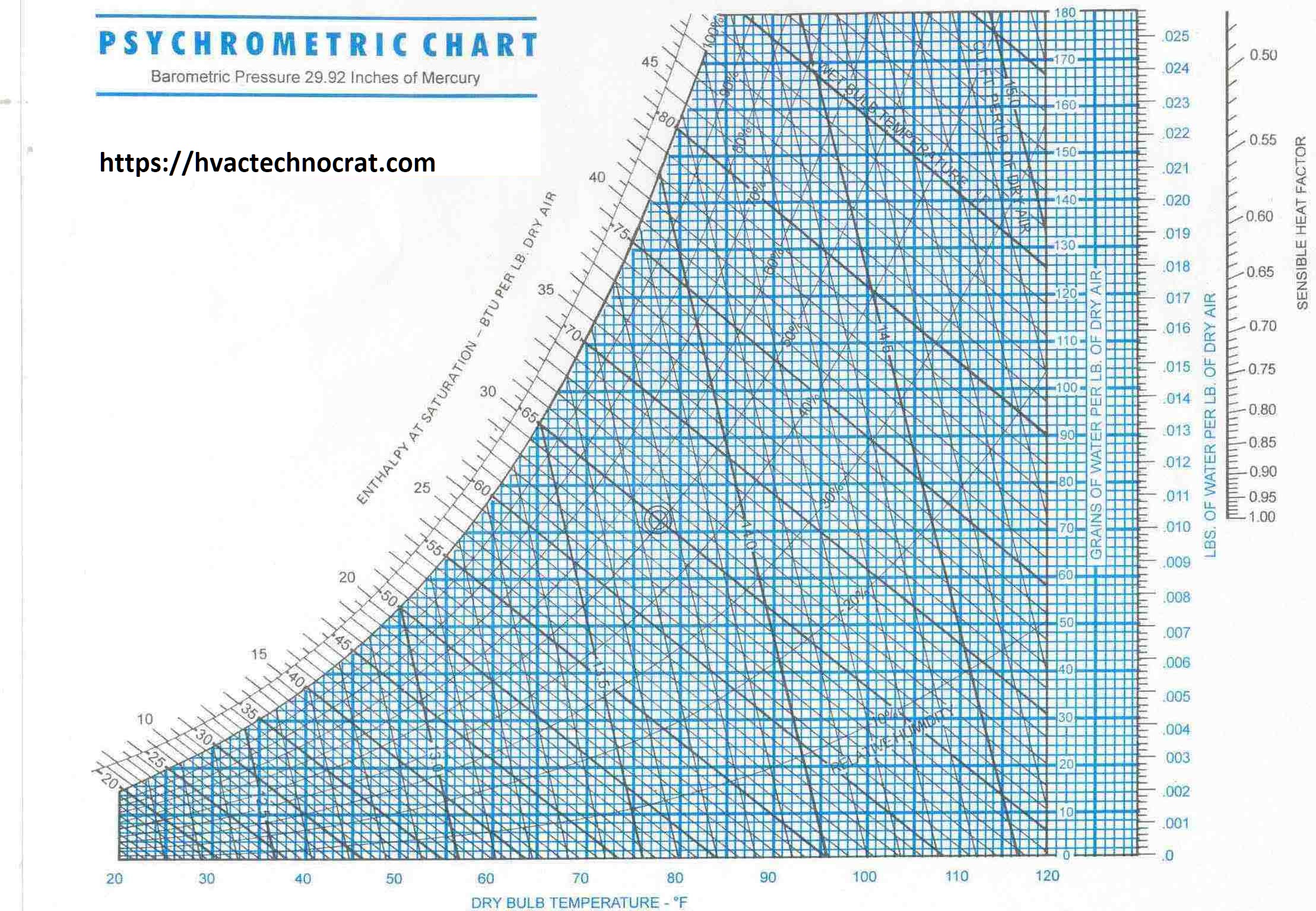
    Psychrometry: Unlocking the Secrets for HVAC Systems

    Psychrometry guide for HVAC systems with a detailed analysis of air properties and processes.

    In the world of HVAC (Heating, Ventilation, and Air Conditioning) systems, Psychrometry plays a crucial role. It involves the study of air properties and their interactions with moisture, which is fundamental in designing and operating HVAC systems efficiently. This article delves into the basics of Psychrometry, its role in HVAC, various Psychrometric processes, applications, specifications, and much more.

    What are the Basics of Psychrometry in HVAC?

    Psychrometry, a branch of science dealing with the properties of air-water vapor mixtures, plays a critical role in HVAC (Heating, Ventilation, and Air Conditioning) systems. Understanding psychrometry helps engineers and technicians design, analyze, and optimize HVAC systems to ensure efficient and effective climate control. The fundamental elements of psychrometry include parameters such as temperature, humidity, enthalpy, and dew point, which collectively describe the thermodynamic properties of moist air. In HVAC applications, psychrometry allows for precise control of air quality and comfort levels, which are essential for both residential and commercial environments.

    What is the Role of Psychrometry in HVAC Systems?

    The role of psychrometry in HVAC systems is multifaceted. It involves the measurement and Humidity Control and Temperature control to achieve desired indoor air conditions. By using psychrometric principles, HVAC professionals can predict how air will behave under various conditions, enabling them to design systems that maintain optimal indoor climates. This includes ensuring proper humidity levels to prevent mold growth, maintaining comfortable temperatures, and ensuring efficient energy use. Psychrometry also helps in diagnosing system issues and optimizing performance by analyzing air properties and their changes through HVAC processes.

    What Types of Psychrometric Processes are Used in HVAC?

    Several psychrometric processes are integral to HVAC systems. These include sensible heating and cooling, where the air temperature is changed without altering its moisture content. Latent heating and cooling involve changes in the moisture content of the air without affecting its temperature. Other processes include humidification, dehumidification, mixing of air streams, and adiabatic cooling. Each process can be plotted and analyzed on a psychrometric chart, providing a visual representation of the air’s condition and helping to determine the necessary changes to achieve desired outcomes in HVAC systems.

    Why psychrometry chart in used in HVAC?

    The psychrometric chart is essential in HVAC engineering for several reasons:

    Understanding Air Properties: It graphically represents thermodynamic properties of moist air, including dry bulb temperature, wet bulb temperature, relative humidity, specific humidity, dew point temperature, and enthalpy. This visualization helps professionals analyze and predict air behavior in various conditions.
    Design and Analysis of HVAC Systems: The chart is crucial for designing and analyzing HVAC systems. It allows engineers to determine the conditions for air treatment processes like cooling, heating, humidification, and dehumidification. This aids in accurately assessing air property changes and selecting the right equipment and settings for optimal indoor air quality and thermal comfort.
    Energy Efficiency and Optimization: Psychrometric charts help identify opportunities for energy efficiency. By understanding the interactions between temperature and humidity, professionals can optimize heat exchange and moisture control processes, reducing energy consumption and improving system performance.
    In summary, the psychrometric chart is vital for visualizing air properties, designing HVAC systems, and enhancing energy efficiency.

    What key processes can be marked on a psychrometric chart?

    A psychrometric chart visually represents the thermodynamic properties of moist air and illustrates key processes. Sensible heating and cooling processes are depicted as horizontal lines, while humidification and dehumidification are shown as vertical lines. The chart also highlights processes like evaporative cooling and adiabatic mixing, helping engineers to analyze and design HVAC systems effectively. The key processes can be marked on a psychrometric chart, each representing different changes in the air properties. Here is a list of these processes:

    1. Sensible Heating
    2. Sensible Cooling
    3. Humidification
    4. Dehumidification
    5. Cooling and Dehumidification
    6. Heating and Humidification
    7. Adiabatic Mixing of Two Air Streams
    8. Evaporative Cooling
    9. Chemical Dehumidification
    10. Cooling with Air Washer
    11. Heating with Steam Injection
    12. Cooling with Dehumidifier
    13. Condensation
    14. Heating and Dehumidification
    15. Air Mixing (Mixing of Two Air Streams at Different Conditions)
    These processes help in understanding and visualizing the changes in air properties such as temperature, humidity, and enthalpy during various HVAC operations.

    What are the Applications of Psychrometry in HVAC Design?

    Psychrometry has numerous applications in HVAC design. It is used to:

    By understanding and applying psychrometric principles, HVAC engineers can create systems that are both efficient and effective, providing optimal indoor environments.

    What are the Specifications for Psychrometric Analysis in HVAC?

    Psychrometric analysis in HVAC involves several specifications, including:

    • Accurate measurement of air properties
    • Proper selection of psychrometric charts
    • Use of precise calculation methods
    • Consideration of environmental factors
    • Adherence to industry standards and guidelines

    These specifications ensure that psychrometric analysis is reliable and effective, leading to well-designed HVAC systems that meet the desired performance criteria.

    What are the Advantages and Disadvantages of Using Psychrometry in HVAC?

    Psychrometry offers several advantages in HVAC, including:

    • Precise control of indoor climates
    • Improved energy efficiency
    • Enhanced occupant comfort
    • Better air quality management
    • Effective troubleshooting and system optimization

    However, there are also some disadvantages, such as:

    • Complexity in understanding and applying psychrometric principles
    • Need for accurate measurements and calculations
    • Potential for errors if not properly executed

    Despite these challenges, the benefits of using psychrometry in HVAC systems far outweigh the drawbacks, making it an essential aspect of modern HVAC design and operation.

    What Information is Typically Included in a Psychrometric Chart?

    A psychrometric chart typically includes information on:

    • Dry-bulb temperature
    • Wet-bulb temperature
    • Relative humidity
    • Specific humidity
    • Dew point temperature
    • Enthalpy
    • Volume of moist air

    This information allows engineers to analyze air properties and make informed decisions about HVAC system design and operation.

    What are the Main Parameters Involved in Psychrometric Processes?

    The main parameters involved in psychrometric processes include:

    • Dry-bulb temperature
    • Wet-bulb temperature
    • Relative humidity
    • Specific humidity
    • Dew point temperature
    • Enthalpy

    These parameters describe the thermodynamic properties of air and are essential for understanding and controlling HVAC systems.

    What Inputs are Essential for Psychrometric Analysis in HVAC?

    Essential inputs for psychrometric analysis in HVAC include:

    • Initial and desired air conditions
    • Environmental factors (e.g., outdoor temperature and humidity)
    • System specifications (e.g., airflow rates and equipment capacities)
    • Load requirements (e.g., heating and cooling loads)

    These inputs help engineers accurately analyze and design HVAC systems to meet specific performance criteria.

    What Design Considerations are Critical for Psychrometric Processes?

    Critical design considerations for psychrometric processes include:

    • Accurate measurement of air properties
    • Proper selection of psychrometric charts and tools
    • Consideration of environmental and load factors
    • Adherence to industry standards and guidelines

    These considerations ensure that psychrometric analysis is reliable and effective, leading to well-designed HVAC systems.

    What Design Parameters are Influenced by Psychrometry?

    Design parameters influenced by psychrometry include:

    • Heating and cooling loads
    • Ventilation rates
    • Humidity control requirements
    • Energy efficiency measures
    • Equipment selection and sizing

    By understanding and applying psychrometric principles, HVAC engineers can optimize these parameters to achieve desired performance outcomes.

    How are Unit Conversions Handled in Psychrometric Calculations?

    Unit conversions in psychrometric calculations are typically handled using conversion factors and formulas. Engineers must ensure that all units are consistent and accurately converted to maintain the integrity of the analysis. Common conversions include temperature (Celsius to Fahrenheit), pressure (Pascals to psi), and energy (Joules to BTUs).

    How is Capacity Calculation Performed Using Psychrometric Charts?

    Capacity calculation using psychrometric charts involves determining the amount of heating or cooling required to achieve desired air conditions. This is done by plotting the initial and desired air states on the chart and analyzing the processes needed to transition between these states. The chart provides a visual representation of the energy changes involved, allowing engineers to calculate the necessary capacity for HVAC equipment.

    What Codes and Standards Govern Psychrometric Analysis in HVAC?

    Several codes and standards govern psychrometric analysis in HVAC, including:

    • ASHRAE (American Society of Heating, Refrigerating, and Air-Conditioning Engineers) standards
    • ISO (International Organization for Standardization) standards
    • Local and national building codes

    These standards ensure that psychrometric analysis is conducted in a consistent and reliable manner, leading to safe and effective HVAC system design and operation.

    What is Included in a Psychrometry Chart?

    A psychrometry chart includes :

    • Dry-bulb temperature lines
    • Wet-bulb temperature lines
    • Relative humidity curves
    • Specific humidity lines
    • Dew point temperature lines
    • Enthalpy lines
    • Volume of moist air lines

    This comprehensive representation of air properties helps engineers analyze and design HVAC systems.

    How is a Psychrometric Chart Created?

    A psychrometric chart is created by plotting the relationships between various air properties on a graph. This involves drawing lines for dry-bulb temperature, wet-bulb temperature, relative humidity, specific humidity, dew point temperature, enthalpy, and volume of moist air. The chart is typically developed using empirical data and mathematical models to accurately represent the thermodynamic properties of moist air.

    What are the Leading Software Tools Available for Psychrometric Analysis?

    Leading software tools for psychrometric analysis include:

    • ASHRAE’s Psychrometric Analysis Tool
    • Carrier’s HVAC System Design Software
    • Trane’s TRACE 700
    • Elite Software’s PsyChart

    These tools provide advanced features for analyzing air properties, designing HVAC systems, and optimizing performance based on psychrometric principles.

    What Should be Included in Design Checklists for Psychrometric Calculation?

    Design checklists for psychrometric calculation should include:

    • Accurate measurement of air properties
    • Selection of appropriate psychrometric charts and tools
    • Consideration of environmental and load factors
    • Adherence to industry standards and guidelines
    • Documentation of all calculations and assumptions

    These checklists ensure that psychrometric analysis is conducted accurately and reliably, leading to effective HVAC system design.

    What Supporting Details are Necessary for Accurate Psychrometric Analysis?

    Supporting details necessary for accurate psychrometric analysis include:

    • Accurate measurements of air properties
    • Detailed information on environmental conditions
    • Comprehensive data on system specifications and load requirements
    • Use of reliable psychrometric charts and tools

    These details ensure that psychrometric analysis is precise and reliable, leading to effective HVAC system design and operation.

    What Procedures are Recommended for Psychrometric Systems?

    Recommended procedures for psychrometric systems include:

    • Regular calibration and maintenance of measurement instruments
    • Accurate measurement and documentation of air properties
    • Use of standardized psychrometric charts and tools
    • Adherence to industry standards and guidelines
    • Continuous monitoring and optimization of system performance

    These procedures ensure that psychrometric systems operate efficiently and effectively, maintaining desired indoor climates and energy efficiency.

    How is Performance Monitoring Carried Out in Systems Utilizing Psychrometry?

    Performance monitoring in systems utilizing psychrometry involves:

    • Regular measurement of air properties
    • Continuous comparison of measured values with desired conditions
    • Use of sensors and data logging equipment
    • Analysis of system performance data
    • Implementation of corrective actions as needed

    By monitoring performance, engineers can ensure that HVAC systems operate efficiently and effectively, maintaining optimal indoor climates.

    How is Lifecycle Analysis Performed for Systems Involving Psychrometry?

    Lifecycle analysis for systems involving psychrometry includes:

    • Evaluation of system performance over time
    • Assessment of energy consumption and efficiency
    • Analysis of maintenance and operational costs
    • Consideration of environmental impacts
    • Identification of opportunities for improvement

    By conducting lifecycle analysis, engineers can optimize HVAC systems for long-term performance and sustainability.

    What Energy Efficiency Measures are Relevant to Psychrometric Processes?

    Energy efficiency measures relevant to psychrometric processes include:

    • Optimizing system design to reduce energy consumption
    • Implementing advanced control strategies
    • Regular maintenance and calibration of equipment
    • Use of energy-efficient components and materials
    • Monitoring and optimizing system performance

    These measures help to reduce energy consumption and enhance the efficiency of HVAC systems, contributing to sustainability and cost savings.

    How Can Systems be Upgraded or Retrofitted to Improve Psychrometric Performance?

    Systems can be upgraded or retrofitted to improve psychrometric performance by:

    • Replacing outdated components with energy-efficient alternatives
    • Implementing advanced control strategies
    • Enhancing insulation and sealing to reduce energy losses
    • Regular maintenance and calibration of equipment
    • Monitoring and optimizing system performance

    These upgrades and retrofits can significantly improve the efficiency and effectiveness of HVAC systems, ensuring optimal indoor climates and energy savings.

    What is the Environmental Impact of Using Psychrometric Analysis in HVAC?

    The environmental impact of using psychrometric analysis in HVAC includes:

    By optimizing HVAC systems using psychrometric analysis, engineers can contribute to environmental sustainability and reduce the overall impact of building operations.

    What Safety Factor Considerations are Necessary for Psychrometric Processes?

    Safety factor considerations for psychrometric processes include:

    • Ensuring accurate measurement and calculation of air properties
    • Adherence to industry standards and guidelines
    • Regular maintenance and calibration of equipment
    • Monitoring system performance and implementing corrective actions as needed
    • Consideration of environmental and load factors

    These considerations ensure that psychrometric processes are safe and reliable, leading to well-designed and effective HVAC systems.

    FAQ

    What do you mean by psychrometry?

    Psychrometry is the study of the properties of air-water vapor mixtures, crucial for understanding and controlling indoor climates in HVAC systems. It involves parameters like temperature, humidity, enthalpy, and dew point.

    What is the psychometric process?

    The psychrometric process involves analyzing and manipulating the properties of air, such as temperature and humidity, to achieve desired indoor conditions. This includes processes like heating, cooling, humidification, and dehumidification.

    What is the use of a psychrometer?

    A psychrometer is an instrument used to measure the moisture content in the air, typically involving dry-bulb and wet-bulb thermometers. It helps determine relative humidity and other psychrometric properties.

    What are the applications of psychrometry?

    Applications of psychrometry include HVAC system design, environmental control in industrial processes, agricultural applications, and ensuring indoor air quality and comfort in residential and commercial buildings.

    Psychrometry ppt

    A psychrometry PowerPoint presentation typically includes an overview of psychrometric principles, applications in HVAC systems, and examples of psychrometric charts and processes. It serves as an educational tool for understanding psychrometry in HVAC design.

    Psychrometric chart

    A psychrometric chart is a graphical representation of the thermodynamic properties of moist air, used to analyze air conditioning processes. It includes parameters like temperature, humidity, and enthalpy, helping engineers design and optimize HVAC systems.

    Psychrometry properties

    Psychrometric properties include dry-bulb temperature, wet-bulb temperature, relative humidity, specific humidity, dew point temperature, and enthalpy. These properties describe the state of air-water vapor mixtures and are essential for HVAC analysis.

    Psychrometric calculator

    A psychrometric calculator is a tool, often software-based, that calculates the properties of air-water vapor mixtures. It helps engineers determine parameters like relative humidity, dew point, and enthalpy based on input conditions.

    Psychrometry pronunciation

    Psychrometry is pronounced as “sy-krom-i-tree,” with emphasis on the second syllable. It combines the Greek words “psyche” (air) and “metron” (measure).

    Psychrometric chart meaning

    The psychrometric chart represents the properties of moist air and their relationships . It helps visualize and analyze processes like heating, cooling, humidification, and dehumidification in HVAC systems.

    Psychrometric chart metric

    A psychrometric chart in metric units uses Celsius for temperature and grams of water per kilogram of dry air for specific humidity. It is used internationally for HVAC analysis and design.

    Psychrometric chart download

    Psychrometric charts can be downloaded from various sources, including HVAC software providers and industry organizations like ASHRAE. These charts are available in both metric and imperial units.

    Psychrometric chart online

    Online psychrometric charts are interactive tools available on websites and software platforms. They allow users to input conditions and visualize air properties and processes dynamically.

    Printable Psychrometric chart

    Printable psychrometric charts are static versions available for download and printing. They provide a handy reference for engineers and technicians working on HVAC systems, helping with on-site analysis and design.

    Conclusion

    Psychrometry is a fundamental aspect of HVAC system design and operation, providing essential insights into the properties of air-water vapor mixtures. By understanding and applying psychrometric principles, engineers can design efficient and effective HVAC systems that ensure optimal indoor climates, energy efficiency, and occupant comfort. The use of psychrometric charts, advanced software tools, and adherence to industry standards and guidelines are crucial for accurate psychrometric analysis. Despite the complexities involved, the benefits of psychrometry in HVAC far outweigh the challenges, making it an indispensable tool for modern climate control and environmental management.

    About The Author

    Omprakash Ramagiri; as the Founder of HVAC Technocrats, I bring over 18 years of experience as a Mechanical Engineer specializing in HVAC (Central Air-conditioning) for commercial, cleanrooms, data centers, and Petrochemical industries. Throughout my career, I’ve held pivotal roles at companies like TATA Consulting Engineers, MW Zander (for Cleanroom solutions), Bluestar Malaysia, and ETA in Dubai. I’ve managed international HVAC projects and gained valuable exposure in dynamic markets like Dubai and Saudi Arabia. With a passion for excellence and a commitment to innovative solutions, I specialize in designing Class 10K & 100K Cleanrooms for various industries. Connect with me to explore collaborations in HVAC design, project sales, and consultancy. Click to visit the Author’s Linkedin page


    Disclaimer: The pictures used are for illustrative purposes only. They may not depict actual products or situations and are meant for educational purposes. Actual products, situations, or outcomes may differ.

    Heat Load Calculation: Everything You Need to Know

    Professionals working on heat load calculation and estimation in HVAC systems

    Heat load calculation, a fundamental aspect of HVAC system design, involves calculating the heat energy required to maintain desired indoor temperatures. This process starts by understanding the space’s dimensions, occupancy levels, and usage patterns. Factors like heat transfer coefficients, building orientation, sunlight exposure, insulation quality, and local climate also play a crucial role. Accurate heat load estimation ensures optimal HVAC system performance, energy efficiency, and occupant comfort. The goal is to size the HVAC system correctly, avoiding over or under-sizing, which can lead to inefficiency and increased costs.

    What role does heat load estimation play in HVAC?

    Heat load estimation is pivotal in HVAC system design and operation. It determines the capacity required to effectively heat or cool a space. Proper estimation helps in selecting the appropriate HVAC equipment, ensuring it operates efficiently. It also impacts energy consumption, operational costs, and indoor comfort levels. Incorrect heat load calculations can lead to overburdened systems, frequent breakdowns, and increased energy bills. Therefore, accurate heat load estimation, considering factors like the heat transfer coefficient and building orientation, is essential for achieving optimal performance, prolonging equipment lifespan, and maintaining a comfortable indoor environment.

    What types of heat loads need to be considered?

    During HVAC system design, various heat loads must be considered, including internal sources like occupants, lighting, and equipment, as well as external factors such as sunlight, ambient temperature, and wind. Sensible heat load refers to the temperature changes, while latent heat load involves humidity control. The specific humidity, fresh air quantity, and dehumidified air quantity are also critical factors. Both types affect the overall HVAC system performance. Understanding these different heat loads is crucial for precise heat load estimation, ensuring the system can handle both temperature and humidity variations efficiently.

    What are the applications of heat load estimation in various projects?

    Heat load estimation is applied in diverse projects, from residential buildings to commercial spaces and industrial facilities. In residential settings, it ensures home comfort and energy efficiency. In commercial projects, accurate estimation supports optimal HVAC performance in offices, retail spaces, and hospitality venues. Industrial applications involve precise control of environmental conditions to maintain product quality and safety. Each project type has unique requirements, making tailored heat load estimation essential for effective HVAC system design and operation. Factors like room dimensions, fresh air changes, and specific humidity levels are particularly critical in these applications.

    What specifications are required for accurate heat load estimation?

    Accurate heat load estimation requires detailed specifications, including building dimensions, materials, insulation levels, and occupancy patterns. Additionally, information on internal heat gains from equipment, lighting, and people is essential. External factors like local climate, sunlight exposure, and wind impact must be considered. Advanced software and tools, such as Carrier E-20, facilitate precise calculations. Key parameters like the heat transfer coefficient, bypass factor for cooling coils, and apparatus dew point must be included. Adhering to industry standards and guidelines ensures consistency and reliability in the estimation process, leading to optimal HVAC system performance.

    What are the advantages and disadvantages of precise heat load estimation?

    Precise heat load estimation offers several advantages. It ensures the HVAC system is correctly sized, enhancing energy efficiency and reducing operational costs. Accurate calculations improve indoor comfort by maintaining consistent temperature and humidity levels. However, the process can be complex, requiring detailed data and advanced tools. Inaccurate estimation can lead to over or under-sizing, resulting in inefficiency, higher costs, and discomfort. Despite these challenges, the benefits of precise heat load estimation, including factors like dry bulb and wet bulb temperatures, outweigh the drawbacks, making it a critical aspect of HVAC system design.

    What inputs are required for heat load estimation?

    Heat load estimation requires several inputs, including building dimensions, construction materials, and insulation quality. Occupancy levels, usage patterns, and internal heat gains from equipment and lighting are also crucial. External factors like local climate, sunlight exposure, and wind direction impact the calculations. Parameters like relative humidity, specific humidity, and fresh air quantity must be included. Advanced tools and software help process these inputs accurately. Adhering to industry standards and guidelines ensures consistency and reliability in the estimation process, leading to optimal HVAC system design and performance.

    What are the main parameters involved in heat load estimation?

    Main parameters in heat load estimation include building dimensions, occupancy levels, and internal heat gains. External factors like local climate, sunlight exposure, and wind impact also play a role. Sensible heat load pertains to temperature changes, while latent heat load involves humidity control. Key parameters like the bypass factor for cooling coils, apparatus dew point, and specific humidity must be considered. Accurate data on these parameters is essential for precise calculations. Using advanced tools and adhering to industry standards ensures reliability and consistency in the estimation process, leading to efficient HVAC system design and operation.

    What is Carrier E-20 calculation sheet for heat load estimation?

    The Carrier E-20 calculation sheet is a widely-used tool for heat load estimation. It helps HVAC professionals accurately calculate the amount of heat energy required to maintain desired indoor conditions. The sheet includes inputs for building dimensions, materials, insulation levels, occupancy, and internal heat gains. External factors like local climate and sunlight exposure are also considered. Parameters like dry bulb and wet bulb temperatures, relative humidity, and specific humidity are included. By processing these inputs, the Carrier E-20 sheet provides precise heat load calculations, ensuring optimal HVAC system design and performance.

    What design considerations are essential for accurate heat load estimation?

    Accurate heat load estimation requires several design considerations. These include building dimensions, materials, and insulation levels. Occupancy patterns and internal heat gains from equipment and lighting are also crucial. External factors like local climate, sunlight exposure, and wind direction impact the calculations. Parameters like sensible heat ratio, apparatus dew point, and specific humidity must be considered. Advanced tools and software help process these inputs accurately. Adhering to industry standards and guidelines ensures reliability and consistency in the estimation process, leading to efficient HVAC system design and operation.

    What design parameters should be factored in during heat load estimation?

    Design parameters essential for heat load estimation include building dimensions, materials, and insulation quality. Occupancy levels, usage patterns, and internal heat gains from equipment and lighting are crucial. External factors like local climate, sunlight exposure, and wind direction impact the calculations. Sensible heat load pertains to temperature changes, while latent heat load involves humidity control. Key parameters like specific humidity, fresh air quantity, and dehumidified air quantity must be considered. Accurate data on these parameters ensures precise calculations, leading to optimal HVAC system design and performance.

    What unit conversions are necessary for heat load estimation?

    Unit conversions play a critical role in heat load estimation. Converting between units like BTU, kW, and tons of refrigeration ensures accurate calculations. For instance, 1 BTU/hr equals 0.000293 kW. Understanding these conversions is essential for professionals using different measurement systems. Advanced tools and software often include built-in conversion features, simplifying the process. Accurate unit conversions ensure reliability in heat load calculations, leading to efficient HVAC system design and operation. Parameters like dry bulb and wet bulb temperatures, relative humidity, and specific humidity may also require unit conversions.

    What methods are used for capacity calculation in heat load estimation?

    Several methods are employed for capacity calculation in heat load estimation. The degree-day method estimates heating and cooling requirements based on historical weather data. The load factor method considers internal and external heat gains. Advanced software tools, like Carrier E-20, facilitate precise calculations by processing detailed inputs. Each method has its advantages and applications, ensuring accurate heat load estimation for various project types. Key parameters like dry bulb and wet bulb temperatures, specific humidity, and fresh air changes must be included. Using the appropriate method enhances HVAC system performance and energy efficiency.

    What codes and standards govern heat load estimation?

    Heat load estimation is governed by various codes and standards. The American Society of Heating, Refrigerating and Air-Conditioning Engineers (ASHRAE) and the Indian Society of Heating, Refrigerating and Air Conditioning Engineers (ISHRAE) provide guidelines for accurate calculations. These standards ensure consistency, reliability, and safety in HVAC system design. Adhering to these codes helps professionals achieve precise heat load estimations, leading to efficient and compliant HVAC installations. Key parameters like dry bulb and wet bulb temperatures, specific humidity, and fresh air changes are included in these guidelines. Access more information on ASHRAE and ISHRAE.

    What are the electrical parameters involved in heat load estimation?

    Electrical parameters are crucial in heat load estimation. These include power consumption of HVAC equipment, lighting, and other electrical devices. Understanding the electrical load helps in selecting appropriate HVAC equipment and ensuring it operates efficiently. Parameters like power factor, voltage, and current ratings are essential. Accurate estimation of these parameters ensures optimal system performance and energy efficiency. Additionally, factors like the total connected load and peak demand must be considered. Using advanced tools and adhering to industry standards help in precise electrical parameter calculations, contributing to effective HVAC system design.

    What software tools are available for heat load estimation?

    Several software tools are available for heat load estimation, streamlining the process and enhancing accuracy. Tools like Carrier E-20, Trane TRACE 700, and HAP (Hourly Analysis Program) are widely used. These tools process detailed inputs, including building dimensions, occupancy patterns, and internal heat gains. They also consider external factors like climate and sunlight exposure. Advanced software often includes built-in unit conversions and adherence to industry standards. Using these tools simplifies the estimation process, ensuring reliable and precise heat load calculations for efficient HVAC system design and operation.

    What are the typical challenges in heat load estimation?

    Heat load estimation can present several challenges. Inaccurate data on building dimensions, occupancy levels, and internal heat gains can lead to incorrect calculations. External factors like local climate and sunlight exposure also add complexity. Ensuring the accuracy of parameters like specific humidity, dry bulb, and wet bulb temperatures is crucial. Additionally, using outdated or incorrect software tools can affect results. Overcoming these challenges requires careful data collection, adherence to industry standards, and the use of advanced estimation tools. Addressing these challenges ensures precise heat load calculations, leading to effective HVAC system design and operation.

    What best practices should be followed for accurate heat load estimation?

    To achieve accurate heat load estimation, several best practices should be followed. Begin with precise data collection on building dimensions, materials, and insulation levels. Consider all internal and external heat gains, including equipment, lighting, and sunlight exposure. Use reliable software tools like Carrier E-20 and adhere to industry standards set by ASHRAE and ISHRAE. Ensure accurate unit conversions and consider all relevant parameters, including specific humidity and fresh air changes. Regularly update software and tools to reflect the latest standards and technologies. Following these best practices leads to reliable heat load calculations, ensuring optimal HVAC system performance.

    Conclusion

    Accurate heat load estimation is essential for efficient HVAC system design and operation. It involves calculating the necessary heat energy to maintain desired indoor conditions, considering various internal and external factors. Precise estimation ensures optimal system performance, energy efficiency, and occupant comfort. By understanding the different heat loads, using advanced tools, and adhering to industry standards, professionals can achieve reliable results. Despite the challenges, following best practices and using appropriate methods ensures successful heat load calculations, contributing to effective and efficient HVAC systems.

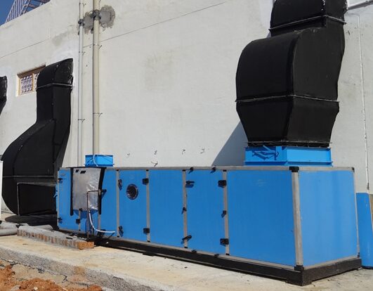
    AHU: Exploring Specifications Which You Need to Know

    Illustration of an AHU in a commercial HVAC system.

    An Air Handling Unit (AHU) is a critical component in HVAC systems, designed to regulate and circulate air. It houses essential elements like fans, filters, heating and cooling coils, and dampers. AHUs are typically used in commercial and industrial settings. They ensure that indoor air quality is maintained by managing temperature, humidity, and air cleanliness. In HVAC systems, AHUs are central to the efficient delivery of conditioned air throughout a building. Therefore, understanding their functionality and role is crucial for optimal HVAC system performance.

    How does an AHU contribute to the overall performance of an HVAC system?

    An AHU significantly enhances the overall performance of an HVAC system by ensuring effective air circulation and quality control. It maintains desired indoor conditions by managing airflow, filtering pollutants, and adjusting temperature and humidity levels. The integration of advanced controls and sensors within AHUs allows precise monitoring and adjustment, leading to energy efficiency and cost savings. Moreover, AHUs support the system’s adaptability to varying external conditions, ensuring comfort and safety for occupants. Therefore, a well-designed AHU is indispensable for maintaining optimal HVAC system performance and energy efficiency.

    What are the different types of AHU available for HVAC systems?

    Several types of AHUs cater to different HVAC system requirements. The main types include packaged AHUs, modular AHUs, and custom-built AHUs. Packaged AHUs are pre-engineered and suitable for standard applications. Modular AHUs offer flexibility with various sections that can be configured as needed. Custom-built AHUs are tailored for specific needs, often used in specialized environments like cleanrooms or laboratories. Additionally, AHUs can be categorized based on their location, such as rooftop units or indoor units. Each type serves distinct purposes, providing versatility in HVAC system design and application.

    Where are AHU commonly used in various industries?

    AHUs are widely used across multiple industries due to their versatility in managing indoor air quality. In commercial buildings like offices and shopping malls, AHUs maintain a comfortable environment for occupants. In healthcare settings, they ensure sterile and clean air, essential for patient safety. AHUs are also crucial in manufacturing plants, especially in cleanrooms and pharmaceutical production, where air purity is paramount. Additionally, they play a significant role in data centers, preserving the optimal temperature for equipment. Thus, AHUs are integral in diverse industries, ensuring environmental control and operational efficiency.

    What key specifications should be considered when selecting an AHU?

    Selecting an AHU involves evaluating several key specifications to ensure optimal performance and compatibility with the HVAC system. Important factors include the unit’s airflow capacity, measured in cubic feet per minute (CFM), and the static pressure it can handle. Additionally, the efficiency of filters, the type and capacity of heating and cooling coils, and the energy efficiency ratio (EER) are critical considerations. Noise levels, ease of maintenance, and the integration of control systems also play a vital role. These specifications help in choosing an AHU that meets the specific requirements of the building and its occupants.

    What are the advantages and disadvantages of using an AHU in an HVAC system?

    Using an AHU in an HVAC system offers several advantages. It provides precise control over air quality, temperature, and humidity, enhancing occupant comfort. AHUs are energy-efficient, contributing to reduced operational costs. They also support modularity and scalability, allowing customization for specific needs. However, there are some disadvantages. AHUs can be complex and expensive to install and maintain. They require regular servicing to ensure optimal performance. Additionally, improperly sized or poorly maintained AHUs can lead to inefficiencies and increased energy consumption. Therefore, a balanced approach is necessary to maximize the benefits of AHUs.

    What information is typically included in an AHU technical data sheet?

    An AHU technical data sheet provides comprehensive details about the unit’s specifications and performance characteristics. Key information includes the airflow rate, static pressure, heating and cooling capacities, and filter efficiency. It also outlines the electrical requirements, including voltage, power consumption, and control options. The data sheet includes dimensions, weight, and installation guidelines. Performance curves, noise levels, and maintenance schedules are also detailed. This information is crucial for selecting, installing, and maintaining the AHU, ensuring it meets the specific needs of the HVAC system and the building it serves.

    What are the main components of an AHU?

    An AHU comprises several main components essential for its operation. The primary components include fans, which drive the airflow, and filters, which remove particulates from the air. Heating and cooling coils adjust the temperature and humidity levels. Dampers control the airflow and pressure within the unit. Additionally, humidifiers add moisture to the air when needed. Sensors and control systems monitor and regulate the performance of these components. Each part plays a critical role in ensuring the AHU functions efficiently, providing a comfortable and healthy indoor environment.

    What are the critical sub-components within an AHU?

    Within an AHU, several critical sub-components ensure its efficient operation. These include the fan motor, which powers the fans, and the belt drive system that transmits this power. Heat exchangers are crucial for transferring thermal energy between the air and the coils. Air filters, including pre-filters and high-efficiency particulate air (HEPA) filters, are essential for removing contaminants. Additionally, dampers and actuators control airflow and pressure. Control systems and sensors monitor and adjust the unit’s performance. Each sub-component plays a vital role in maintaining the AHU’s functionality and efficiency.

    What are the essential design considerations for an AHU?

    Designing an AHU involves several essential considerations to ensure optimal performance and compatibility with the HVAC system. These include determining the required airflow rate and static pressure, selecting appropriate filters, and choosing the right type and capacity of heating and cooling coils. The design must also consider noise levels, energy efficiency, and ease of maintenance. Additionally, the integration of control systems and sensors is crucial for monitoring and adjusting performance. Properly addressing these factors ensures the AHU meets the specific needs of the building and its occupants, providing a comfortable and healthy indoor environment.

    What design parameters must be considered when planning an AHU?

    When planning an AHU, several design parameters are critical to ensure optimal performance. These include the airflow rate, static pressure, and temperature and humidity control requirements. The type and efficiency of filters, the capacity of heating and cooling coils, and the energy efficiency ratio (EER) are also important. Noise levels, ease of maintenance, and the integration of control systems and sensors are crucial considerations. Properly addressing these parameters ensures the AHU meets the specific needs of the building and its occupants, providing a comfortable and healthy indoor environment.

    What unit conversions are necessary for AHU design and specification?

    Designing and specifying an AHU requires several unit conversions to ensure accuracy. Common conversions include airflow rate from cubic feet per minute (CFM) to cubic meters per hour (m³/h) and static pressure from inches of water column (in. w.c.) to Pascals (Pa). Temperature conversions between Fahrenheit (°F) and Celsius (°C) are often necessary. Additionally, energy efficiency ratios (EER) may need to be converted to coefficient of performance (COP). These conversions ensure that the AHU specifications align with industry standards and meet the specific needs of the building and its occupants.

    What methods are used to calculate the capacity of an AHU?

    Calculating the capacity of an AHU involves several methods to ensure accurate sizing and performance. One common method is the heat load calculation, which considers the building’s thermal requirements based on factors like occupancy, equipment, and insulation. The airflow rate is determined by calculating the volume of air needed to maintain desired indoor conditions. Additionally, the cooling and heating capacities are calculated based on the temperature and humidity control requirements. These calculations ensure the AHU is appropriately sized and capable of meeting the specific needs of the building and its occupants.

    What codes and standards govern the use of AHU in HVAC systems?

    The use of AHUs in HVAC systems is governed by several codes and standards to ensure safety, efficiency, and performance. Key standards include those set by the American Society of Heating, Refrigerating, and Air-Conditioning Engineers (ASHRAE) and the Indian Society of Heating, Refrigerating, and Air Conditioning Engineers (ISHRAE). These standards provide guidelines for design, installation, and maintenance. Additionally, building codes like the International Building Code (IBC) and local regulations may apply. Adhering to these codes and standards ensures that AHUs meet the necessary safety and performance requirements, providing a comfortable and healthy indoor environment.

    What is a general arrangement drawing for an AHU?

    A general arrangement drawing for an AHU provides a detailed visual representation of the unit’s layout and components. It includes dimensions, placement of filters, motor, fans, coils, drain pan, limit switch, lamp, motor base channels, dampers and other elements. The drawing shows the overall configuration, including duct connections, access doors, and control panels. It also indicates service and maintenance areas, ensuring ease of access. This drawing is crucial for the proper installation and integration of the AHU within the HVAC system. It helps ensure that all components are correctly placed and that the unit functions efficiently, providing a comfortable and healthy indoor environment.

    What information is conveyed in an AHU schematic drawing?

    An AHU schematic drawing provides a detailed representation of the unit’s internal components and their connections. It includes diagrams of fans, filters, heating and cooling coils, dampers, and control systems. The schematic shows the airflow path, indicating how air moves through the unit. It also details electrical connections, including power supply and control wiring. This drawing is essential for understanding the AHU’s operation and for troubleshooting any issues. It ensures that all components are correctly connected and functioning as intended, contributing to the overall performance of the HVAC system.

    What is included in the electrical scope of works for an AHU?

    The electrical scope of works for an AHU outlines the necessary electrical requirements and connections. It includes details on power supply, such as voltage and phase, and the unit’s electrical load. The scope also specifies the wiring connections for fans, motors, control panels, and sensors. It includes requirements for grounding, circuit protection, and emergency shutdown systems. This document ensures that the AHU is correctly wired and complies with electrical codes and standards. Properly addressing the electrical scope of works is crucial for the safe and efficient operation of the AHU within the HVAC system.

    Who are the leading manufacturers of AHU?

    Several leading manufacturers specialize in producing high-quality AHUs for various HVAC applications. Notable names include

    • Carrier
    • Trane
    • Daikin
    • Johnson Controls
    • York
    known for their advanced technology and reliable performance and are also prominent manufacturers, offering a range of AHUs tailored for different industries. Other key players include
    • Zeco
    • Greenheck
    • McQuay
    • Bluestar
    • Voltas
    • Systemair
    each providing innovative solutions to meet specific air handling needs. These manufacturers are renowned for their commitment to quality, energy efficiency, and sustainability, ensuring that their AHUs deliver optimal performance and reliability in diverse applications.

    What is a bill of material for an AHU?

    A bill of material (BOM) for an AHU lists all the components and materials required for its construction and installation. It includes detailed descriptions and quantities of parts like panels, fans, motors, filters, coils, and control systems. The BOM also specifies the necessary hardware, such as bolts, brackets, and duct connections. This document is crucial for ensuring that all components are accounted for and available during the assembly and installation process. A comprehensive BOM helps streamline procurement, minimize delays, and ensure the AHU is built and installed correctly, providing efficient and reliable operation.

    What is the purpose of a shop drawing for an AHU?

    A shop drawing for an AHU provides detailed instructions for its fabrication and assembly. It includes precise dimensions, materials, and construction techniques. The drawing outlines the placement of components, such as fans, coils, and filters, and specifies the necessary connections and alignments. Shop drawings ensure that the AHU is built according to the design specifications and meets the required performance standards. They are used by manufacturers and contractors to guide the construction process, ensuring accuracy and consistency. Properly executed shop drawings are essential for delivering a high-quality AHU that functions efficiently.

    What are the steps involved in the installation of an AHU?

    The installation of an AHU involves several critical steps to ensure proper setup and operation. First, the unit is positioned and anchored in the designated location. Duct connections are made, ensuring airtight seals. Electrical wiring is completed according to the electrical scope of works. Next, the fans, coils, filters, and control systems are installed and connected. The unit is then tested for leaks, airflow, and operational functionality. Finally, adjustments are made to optimize performance, and the AHU is commissioned for use. Following these steps ensures that the AHU operates efficiently and meets the HVAC system’s requirements.

    What should be included in an AHU installation checklist?

    An AHU installation checklist ensures all critical tasks are completed for a successful setup. Key items include verifying the correct placement and securing the unit, checking duct connections for airtight seals, and completing electrical wiring according to the scope of works. The checklist also includes installing and connecting fans, coils, filters, and control systems, testing for leaks and airflow, and verifying operational functionality. Finally, adjustments are made to optimize performance, and the unit is commissioned for use. This comprehensive checklist helps ensure that the AHU operates efficiently and meets the HVAC system’s requirements.

    What supporting details are necessary for AHU installation?

    Supporting details for AHU installation include site-specific information such as the unit’s location, mounting requirements, and available space. Detailed diagrams of duct connections, electrical wiring, and control system interfaces are essential. Information on necessary tools, equipment, and materials, including dimensions and quantities, is crucial. Additionally, guidelines for safety procedures, maintenance access, and operational testing are necessary. These details ensure that the AHU installation is carried out accurately and efficiently, minimizing the risk of errors and ensuring optimal performance within the HVAC system.

    What procedures are involved in testing, adjusting, and balancing an AHU?

    Testing, adjusting, and balancing (TAB) an AHU involves several procedures to ensure optimal performance. First, airflow measurements are taken to verify the unit’s output matches the design specifications. Adjustments are made to fan speeds, dampers, and control settings to achieve the desired airflow and pressure. The temperature and humidity levels are checked and adjusted as needed. Filters and coils are inspected for proper installation and functionality. Finally, the entire system is tested under various operating conditions to ensure consistent performance. These procedures help maintain the AHU’s efficiency and reliability within the HVAC system.

    What techniques are used to control noise and vibration in AHU?

    Controlling noise and vibration in AHUs involves several techniques to enhance comfort and efficiency. Acoustic insulation materials are used to line the unit’s casing, reducing noise transmission. Vibration isolation mounts are installed to minimize the transfer of vibrations to the building structure. Additionally, flexible duct connectors help absorb vibrations from the unit’s fans and motors. Properly balancing the fans and ensuring all components are securely fastened also reduces noise and vibration. These techniques are essential for maintaining a quiet and comfortable indoor environment, enhancing the overall performance of the HVAC system.

    What are the recommended maintenance procedures for an AHU?

    Regular maintenance is essential for ensuring the optimal performance and longevity of an AHU. Key procedures include inspecting and cleaning filters, coils, and fans to prevent the buildup of dust and debris. Checking and adjusting belts and pulleys ensures proper alignment and tension. Lubricating moving parts, such as fan bearings and motor shafts, reduces wear and tear. Additionally, verifying the functionality of control systems and sensors is crucial for maintaining accurate performance. Periodic testing and calibration of the unit’s components help identify potential issues early, ensuring reliable operation and energy efficiency.

    What are common troubleshooting and diagnostic techniques for AHUs?

    Troubleshooting and diagnosing AHU issues involve several techniques to identify and resolve problems. Visual inspections are conducted to check for obvious signs of damage or wear. Measuring airflow and static pressure helps detect blockages or leaks in the ductwork. Temperature and humidity readings indicate issues with heating or cooling coils. Electrical tests verify the functionality of motors, fans, and control systems. Additionally, listening for unusual noises and checking vibration levels can reveal mechanical issues. These techniques help pinpoint the cause of problems, allowing for timely repairs and ensuring the AHU operates efficiently.

    What methods are used to monitor the performance of an AHU?

    Monitoring the performance of an AHU involves several methods to ensure it operates efficiently. Sensors and control systems provide real-time data on airflow, temperature, humidity, and pressure. Regular inspections and maintenance checks help identify potential issues early. Performance metrics, such as energy consumption and runtime, are tracked to detect changes in efficiency. Additionally, advanced monitoring systems can alert operators to deviations from normal operating conditions. These methods help maintain the AHU’s performance, ensuring it meets the HVAC system’s requirements and provides a comfortable and healthy indoor environment.

    What is involved in the lifecycle analysis of an AHU?

    Lifecycle analysis of an AHU involves evaluating its performance, costs, and environmental impact from installation to decommissioning. Key factors include the unit’s initial purchase and installation costs, operational and maintenance expenses, and energy consumption. Environmental considerations, such as the materials used and the unit’s efficiency, are also analyzed. The expected lifespan and potential for upgrades or retrofits are evaluated. This comprehensive analysis helps determine the overall value and sustainability of the AHU, guiding decisions on its selection, operation, and replacement within the HVAC system.

    What features of an AHU contribute to energy efficiency?

    Several features of an AHU contribute to its energy efficiency. High-efficiency fans and motors reduce energy consumption while maintaining optimal airflow. Variable speed drives (VSDs) adjust fan speeds based on demand, minimizing energy use. Advanced control systems monitor and regulate the unit’s performance, optimizing energy efficiency. High-efficiency filters reduce pressure drop, decreasing the workload on fans. Additionally, heat recovery systems capture and reuse waste heat, further enhancing energy efficiency. These features help reduce operational costs and environmental impact, ensuring the AHU provides sustainable and efficient performance within the HVAC system.

    What are the benefits of upgrading or retrofitting an AHU?

    Upgrading or retrofitting an AHU offers several benefits, enhancing performance and efficiency. Newer components, such as high-efficiency fans, motors, and filters, reduce energy consumption and operational costs. Advanced control systems improve the unit’s responsiveness and accuracy, ensuring optimal indoor conditions. Retrofitting can also address specific issues, such as noise and vibration control, improving occupant comfort. Additionally, upgrades extend the unit’s lifespan, delaying the need for a complete replacement. These benefits contribute to a more efficient, reliable, and sustainable HVAC system, providing long-term value and improved performance.

    What warranty information should you look for when purchasing an AHU?

    When purchasing an AHU, it is important to consider the warranty information provided by the manufacturer. Look for warranties that cover key components, such as fans, motors, coils, and control systems, for an extended period. Ensure the warranty includes coverage for defects in materials and workmanship. Additionally, check if the warranty provides for labor costs associated with repairs or replacements. Understanding the warranty terms, conditions, and exclusions is crucial for ensuring long-term protection and support. A comprehensive warranty offers peace of mind and safeguards your investment in the AHU, ensuring reliable performance and customer satisfaction.

    What is the environmental impact of using an AHU?

    The environmental impact of using an AHU depends on several factors, including its energy efficiency, materials used, and emissions. High-efficiency units consume less energy, reducing greenhouse gas emissions and lowering operational costs. Sustainable materials, such as recyclable components and environmentally friendly refrigerants, minimize environmental harm. Proper maintenance and regular servicing ensure optimal performance, reducing the unit’s overall impact. Additionally, advanced technologies, such as heat recovery systems, further enhance sustainability. By choosing energy-efficient and environmentally conscious AHUs, you can significantly reduce the environmental footprint of your HVAC system, contributing to a healthier planet.

    What safety considerations must be taken into account when installing an AHU?

    Safety considerations are crucial when installing an AHU to ensure the protection of personnel and equipment. Proper grounding and electrical connections prevent electrical hazards. Adequate clearance around the unit allows for safe access during maintenance and servicing. Using appropriate lifting equipment and techniques ensures safe handling and installation of heavy components. Additionally, following manufacturer guidelines and local codes and standards, such as those set by ASHRAE and ISHRAE, ensures compliance with safety regulations. Implementing safety measures during installation helps prevent accidents, ensuring a safe and efficient operation of the AHU within the HVAC system.

    What spare parts are typically required for AHU maintenance?

    AHU maintenance requires several spare parts to ensure continued performance and reliability. Commonly needed parts include filters, belts, and bearings, which wear out over time. Replacement fans and motors are essential for addressing mechanical failures. Coils and heat exchangers may also need replacement due to corrosion or damage. Control components, such as sensors and actuators, ensure accurate system operation and may require periodic replacement. Keeping a stock of these spare parts enables timely repairs and minimizes downtime, ensuring the AHU operates efficiently and maintains the desired indoor air quality and comfort levels.

    FAQ

    What is the AHU in HVAC?

    The AHU, or Air Handling Unit, in HVAC systems, is a device that conditions and circulates air as part of the heating, ventilation, and air conditioning system. It ensures proper air filtration, temperature control, and humidity regulation to maintain indoor air quality and comfort in buildings.

    What is AHU vs FCU in HVAC?

    AHU (Air Handling Unit) and FCU (Fan Coil Unit) serve different purposes in HVAC systems. AHUs are larger units that handle air conditioning and ventilation for entire buildings, while FCUs are smaller units that condition air for specific spaces or rooms.

    What are the main parts of the AHU?

    The main parts of an AHU include:

    • Fan: Moves air through the unit.
    • Coils: Heat or cool the air.
    • Filters: Remove particles from the air.
    • Dampers: Control airflow.
    • Mixing Chamber: Mixes air for temperature control.
    • Control Panel: Manages the unit’s operation.

    Types of AHU in HVAC systems

    There are several types of AHUs used in HVAC systems:

    • Rooftop Units: Installed on the roof, suitable for large spaces.
    • Modular Units: Flexible and customizable for various applications.
    • Make-up Air Units: Provide fresh air to replace exhaust air.
    • Packaged Units: Contain all components in a single enclosure.

    Role of AHU in HVAC systems

    The AHU plays a crucial role in HVAC systems by conditioning and distributing air throughout the building. It ensures the air is clean, at the right temperature, and maintains proper humidity levels, contributing to occupant comfort and indoor air quality.

    AHU in HVAC systems Wikipedia

    AHU in HVAC systems is extensively covered on Wikipedia, describing its function, components, and various types used in different applications. It provides an in-depth overview of how AHUs integrate into HVAC systems to maintain air quality and comfort in buildings.

    Types of AHU

    Different types of AHUs include:

    • Single Zone Units: Serve specific areas with consistent requirements.
    • Multi-Zone Units: Serve multiple areas with varying needs.
    • Heat Recovery Units: Recover energy from exhaust air.
    • Custom-Built Units: Designed for unique applications or specifications.

    Air handling unit diagram

    An air handling unit diagram illustrates the internal components and airflow path within the unit. It typically includes fans, coils, filters, dampers, and control systems, helping to understand how air moves through the system for effective operation and maintenance.

    Air handling unit working principle

    The working principle of an air handling unit involves drawing air in, conditioning it by heating, cooling, filtering, and regulating humidity, and then distributing it throughout the building. This process ensures consistent indoor air quality and comfort.

    AHU full form in HVAC

    AHU in HVAC stands for Air Handling Unit. It refers to the equipment responsible for air conditioning and ventilation within buildings, ensuring proper air quality and comfort.

    Air handling unit for home

    An air handling unit for home use is designed to provide efficient air conditioning and ventilation specifically for residential spaces. It helps maintain optimal indoor air quality and comfort levels within homes.

    Conclusion

    AHUs are integral components of HVAC systems, providing essential air handling functions for various applications. Understanding their types, specifications, components, and installation requirements is crucial for optimizing performance and efficiency. Proper maintenance, troubleshooting, and monitoring ensure reliable operation and longevity. Upgrading or retrofitting AHUs can enhance energy efficiency, reduce operational costs, and improve indoor air quality. By following industry standards and guidelines, such as those from ASHRAE and ISHRAE, you can ensure safe and compliant AHU installations. Investing in high-quality AHUs with comprehensive warranties and minimal environmental impact contributes to a sustainable and efficient HVAC system.

    About the Author

    Omprakash Ramagiri; as the Founder of HVAC Technocrats, I bring over 18 years of experience as a Mechanical Engineer specializing in HVAC (Central Air-conditioning) for commercial, cleanrooms, data centers, and Petrochemical industries. Throughout my career, I’ve held pivotal roles at companies like TATA Consulting Engineers, MW Zander (for Cleanroom solutions), Bluestar Malaysia, and ETA in Dubai. I’ve managed international HVAC projects and gained valuable exposure in dynamic markets like Dubai and Saudi Arabia. With a passion for excellence and a commitment to innovative solutions, I specialize in designing Class 10K & 100K Cleanrooms for various industries. Connect with me to explore collaborations in HVAC design, project sales, and consultancy. Click to visit the Author’s Linkedin page


    Disclaimer: The pictures used are for illustrative purposes only. They may not depict actual products or situations and are meant for educational purposes. Actual products, situations, or outcomes may differ.

    How to Choose the Right Geothermal HVAC System

    Illustration of Geothermal HVAC System

    Geothermal HVAC systems significantly reduce energy bills by harnessing the stable temperatures found underground. Unlike traditional systems that rely on fluctuating outdoor air temperatures, geothermal systems use the constant temperature of the earth as a heat source in the winter and a heat sink in the summer. This efficient transfer of heat reduces the need for electricity, leading to lower utility costs. Furthermore, geothermal systems have fewer mechanical components, resulting in less wear and tear and lower maintenance costs. The high efficiency of these systems translates to reduced energy consumption, contributing to overall energy efficiency. As energy prices continue to rise, the long-term savings from geothermal HVAC systems become even more significant, making them an attractive option for both residential and commercial applications.

    How do geothermal HVAC systems reduce energy bills and contribute to energy efficiency?

    Geothermal HVAC systems significantly reduce energy bills by harnessing the stable temperatures found underground. Unlike traditional systems that rely on fluctuating outdoor air temperatures, geothermal systems use the constant temperature of the earth as a heat source in the winter and a heat sink in the summer. This efficient transfer of heat reduces the need for electricity, leading to lower utility costs. Furthermore, geothermal systems have fewer mechanical components, resulting in less wear and tear and lower maintenance costs. The high efficiency of these systems translates to reduced energy consumption, contributing to overall energy efficiency. As energy prices continue to rise, the long-term savings from geothermal HVAC systems become even more significant, making them an attractive option for both residential and commercial applications.

    What is the role of geothermal HVAC systems in reducing a building’s carbon footprint?

    Geothermal HVAC systems play a crucial role in reducing a building’s carbon footprint by utilizing renewable energy from the earth. Unlike conventional heating and cooling systems that burn fossil fuels, geothermal systems rely on the earth’s natural heat, which is a sustainable and clean energy source. This drastically reduces greenhouse gas emissions associated with heating and cooling a building. Additionally, the energy efficiency of geothermal systems means less electricity is needed to achieve the same level of comfort, further reducing the reliance on fossil fuel-based power plants. By lowering the demand for fossil fuels and decreasing emissions, geothermal HVAC systems contribute to a more sustainable and environmentally friendly building operation. This makes them an ideal choice for those looking to minimize their environmental impact.

    When should builders consider integrating geothermal HVAC systems in new construction projects?

    Builders should consider integrating geothermal HVAC systems in new construction projects from the initial planning stages. Early integration allows for the design and layout to accommodate the specific requirements of geothermal systems, such as the placement of ground loops. Additionally, incorporating geothermal systems early in the design process can help optimize the overall energy efficiency of the building, as the system can be tailored to the building’s specific heating and cooling loads. The upfront costs of geothermal systems can be offset by the long-term savings on energy bills and potential tax incentives or rebates available for green building practices. Therefore, for projects aiming to achieve high energy efficiency and sustainability standards, geothermal HVAC systems are a valuable consideration from the outset.

    Where are geothermal HVAC systems most beneficial, in residential or commercial buildings?

    Geothermal HVAC systems offer significant benefits for both residential and commercial buildings, but their advantages can be more pronounced in certain contexts. In residential settings, homeowners can experience substantial reductions in energy bills and maintenance costs. The consistent and efficient heating and cooling provided by geothermal systems enhance comfort while reducing reliance on fossil fuels. In commercial buildings, the larger scale of heating and cooling needs can amplify the energy savings and environmental benefits of geothermal systems. Commercial properties often have more space available for installing ground loops, making it easier to implement these systems effectively. Additionally, businesses can benefit from improved indoor air quality and a greener corporate image by adopting geothermal HVAC systems. Therefore, while both residential and commercial buildings can benefit, the scale and environmental impact may be more significant in commercial applications.

    Who decides on incorporating geothermal HVAC systems into building designs, and what factors influence this decision?

    The decision to incorporate geothermal HVAC systems into building designs typically involves architects, engineers, building owners, and sometimes environmental consultants. These stakeholders evaluate various factors, including the project’s budget, energy efficiency goals, and environmental impact. The location of the building site is crucial, as the feasibility of installing geothermal systems depends on the geological conditions and available space for ground loops. Additionally, long-term cost savings, potential incentives or rebates, and the desire to achieve green building certifications can influence the decision. Architects and engineers assess the technical aspects and design integration, while building owners consider the financial and environmental benefits. Collaboration among these parties ensures that the decision to implement geothermal HVAC systems aligns with the overall goals of the project.

    Why are geothermal HVAC systems considered the ultimate sustainable heating and cooling solutions?

    Geothermal HVAC systems are considered the ultimate sustainable heating and cooling solutions due to their unparalleled energy efficiency and minimal environmental impact. These systems utilize the stable temperatures of the earth to provide consistent heating and cooling, drastically reducing the need for fossil fuels and lowering greenhouse gas emissions. The renewable energy source used by geothermal systems ensures a sustainable and reliable solution for temperature control. Additionally, geothermal systems have a longer lifespan compared to traditional HVAC systems, further enhancing their sustainability. Their ability to significantly reduce energy consumption and environmental footprint makes them an ideal choice for those committed to sustainable building practices. The comprehensive benefits of geothermal HVAC systems make them a leading option for achieving energy efficiency and environmental stewardship.

    How do geothermal HVAC systems contribute to long-term cost savings?

    Geothermal HVAC systems contribute to long-term cost savings through their high energy efficiency and low maintenance requirements. By utilizing the earth’s stable temperatures, these systems operate more efficiently than traditional HVAC systems, resulting in lower energy consumption and reduced utility bills. The initial installation costs of geothermal systems can be higher, but the significant savings on energy bills typically offset these costs within a few years. Additionally, geothermal systems have fewer moving parts, leading to lower maintenance costs and longer system lifespan. Over time, the reduced operational and maintenance expenses contribute to substantial long-term cost savings. For property owners, the investment in geothermal HVAC systems can yield financial benefits through decreased energy expenses and increased property value.

    What are the different types of geothermal HVAC systems, and what are their specific advantages?

    There are several types of geothermal HVAC systems, each with its own advantages. The most common types include closed-loop and open-loop systems. Closed-loop systems, which can be further divided into horizontal, vertical, and pond/lake systems, use a continuous loop of piping filled with a heat transfer fluid. Horizontal systems are ideal for properties with ample land, while vertical systems are suitable for smaller plots or where ground conditions require deeper drilling. Pond/lake systems are efficient for properties with access to a water body. Open-loop systems, on the other hand, use groundwater from a well or surface water source, returning it to the ground after heat exchange. Each type offers specific benefits based on site conditions and project requirements, providing versatile solutions for various applications.

    When is a closed-loop geothermal HVAC system preferable over an open-loop system, and why?

    A closed-loop geothermal HVAC system is preferable over an open-loop system when groundwater availability is limited or the quality of groundwater is not suitable for direct use. Closed-loop systems do not rely on a continuous supply of water and are therefore more reliable in areas where water resources are scarce or regulated. Additionally, closed-loop systems are generally easier to maintain since the heat transfer fluid remains in a closed system, reducing the risk of contamination and mineral buildup that can occur in open-loop systems. Closed-loop systems are also more versatile in terms of installation, as they can be adapted to various site conditions, including horizontal or vertical configurations. This flexibility makes closed-loop systems a preferred choice for many installations, ensuring consistent performance and reliability.

    Where are horizontal and vertical geothermal heat pump systems most effective?

    Horizontal geothermal heat pump systems are most effective in areas with ample land space where excavation is feasible. These systems involve laying pipes horizontally in trenches, typically at a depth of four to six feet. They are ideal for residential properties with large yards or commercial sites with available open land. Vertical geothermal heat pump systems, on the other hand, are most effective in areas where land space is limited or where the soil conditions are unsuitable for horizontal trenching. These systems require drilling deep vertical boreholes, making them suitable for urban environments, small properties, or areas with rocky or compact soil. The choice between horizontal and vertical systems depends on land availability, soil conditions, and the specific heating and cooling needs of the building.

    Who benefits the most from using hybrid geothermal HVAC systems in their buildings?

    Hybrid geothermal HVAC systems offer the greatest benefits to buildings with diverse and variable heating and cooling loads. These systems combine geothermal technology with traditional HVAC equipment, optimizing energy efficiency by leveraging the strengths of both systems. Large commercial buildings, such as office complexes, hospitals, and schools, can benefit significantly from hybrid systems due to their varying occupancy and usage patterns. Hybrid systems can provide base load heating and cooling through geothermal means, while supplementary equipment can handle peak loads or extreme weather conditions. This approach maximizes energy savings and ensures consistent comfort levels throughout the year. Additionally, hybrid systems can reduce the size and cost of the geothermal installation, making them an attractive option for projects with budget constraints.

    Why are direct exchange geothermal systems gaining popularity in the HVAC industry?

    Direct exchange (DX) geothermal systems are gaining popularity in the HVAC industry due to their simplicity, efficiency, and cost-effectiveness. Unlike traditional geothermal systems that use a heat transfer fluid, DX systems circulate refrigerant directly through copper tubing buried in the ground. This direct heat exchange minimizes energy losses and increases system efficiency, resulting in lower operating costs and reduced environmental impact. DX systems are also easier to install and maintain compared to closed-loop systems, as they require fewer components and eliminate the need for a secondary heat exchanger. The compact design of DX systems makes them suitable for residential and light commercial applications where space and installation ease are priorities. As energy efficiency standards continue to evolve, DX geothermal systems offer a streamlined solution for achieving sustainable HVAC performance.

    How do geothermal HVAC systems contribute to indoor air quality improvement?

    Geothermal HVAC systems contribute to indoor air quality improvement by reducing the circulation of indoor pollutants and allergens. Unlike traditional HVAC systems that draw air from the outside, geothermal systems exchange heat with the ground, where the air is naturally cleaner and free of contaminants. This process eliminates the introduction of outdoor pollutants into the building’s ventilation system, leading to cleaner indoor air. Additionally, geothermal systems typically include air filtration and purification components as part of their design, further enhancing indoor air quality. By maintaining consistent humidity levels and reducing airborne particles, geothermal HVAC systems create a healthier indoor environment for occupants. Improved indoor air quality can benefit individuals with respiratory conditions or allergies, as well as contribute to overall comfort and well-being in residential and commercial settings.

    Who can benefit from integrating geothermal HVAC systems in industrial facilities?

    Industrial facilities can benefit greatly from integrating geothermal HVAC systems due to their high energy demands and need for reliable temperature control. Geothermal systems provide efficient and consistent heating and cooling, reducing energy consumption and operational costs. Industries that require precise temperature regulation, such as manufacturing, pharmaceuticals, and food processing, can benefit from the stable and efficient performance of geothermal systems. Additionally, the reduced environmental impact and lower greenhouse gas emissions associated with geothermal systems align with corporate sustainability goals. By adopting geothermal HVAC systems, industrial facilities can achieve significant energy savings, enhance operational efficiency, and contribute to environmental stewardship. The long-term cost benefits and environmental advantages make geothermal systems a valuable investment for industrial applications.

    Why are geothermal HVAC systems preferred for maintaining consistent indoor temperatures throughout the year?

    Geothermal HVAC systems are preferred for maintaining consistent indoor temperatures throughout the year due to their ability to leverage the stable temperatures of the earth. Unlike traditional systems that rely on fluctuating outdoor air temperatures, geothermal systems use the constant underground temperature to provide heating and cooling. This ensures a more stable and reliable indoor climate, regardless of seasonal variations. Geothermal systems can efficiently switch between heating and cooling modes, providing seamless comfort all year round. Additionally, the even distribution of heat and cooling through geothermal systems enhances overall comfort levels within the building. The ability to maintain consistent indoor temperatures with high efficiency and reliability makes geothermal HVAC systems a preferred choice for many property owners.

    How do geothermal HVAC systems contribute to enhancing indoor air quality?

    Geothermal HVAC systems contribute to enhancing indoor air quality by eliminating the need for combustion-based heating methods that can release pollutants into the indoor environment. Traditional heating systems, such as furnaces and boilers, can emit carbon monoxide, nitrogen oxides, and other harmful substances that degrade indoor air quality. Geothermal systems, on the other hand, use the earth’s natural heat, providing a clean and safe source of heating and cooling. Additionally, geothermal systems often include air purification and humidity control features, further improving indoor air quality. The consistent and efficient operation of geothermal systems ensures a healthier indoor environment, reducing the risk of respiratory issues and allergies. By providing clean and efficient heating and cooling, geothermal HVAC systems enhance overall indoor air quality.

    What key specifications should be considered when designing a geothermal HVAC system?

    When designing a geothermal HVAC system, several key specifications should be considered to ensure optimal performance and efficiency. These include the size and layout of the ground loop, the type of system (closed-loop or open-loop), and the capacity of the heat pump. The ground loop design must be tailored to the specific site conditions, including soil type, moisture content, and available space. The heat pump capacity should be appropriately matched to the building’s heating and cooling loads to ensure efficient operation. Additionally, the design should consider the integration of auxiliary systems, such as radiant floor heating or domestic hot water. Proper insulation and sealing of ductwork and piping are also crucial to minimize energy losses. By carefully considering these specifications, designers can create a geothermal HVAC system that delivers maximum efficiency and performance.

    When should geothermal HVAC system specifications be customized for unique project needs?

    Geothermal HVAC system specifications should be customized for unique project needs when the standard designs do not meet the specific requirements of the site or the building. Customization is necessary for projects with unique geological conditions, such as rocky or unstable soil, which may require specialized ground loop configurations. Additionally, buildings with unusual heating and cooling loads, such as those with large glass facades or high occupancy rates, may need tailored system capacities and designs. Custom specifications are also essential for integrating geothermal systems with other renewable energy sources, like solar panels, or with advanced building automation systems. By customizing the specifications, designers can ensure that the geothermal HVAC system meets the specific needs of the project, providing optimal performance and efficiency.

    Where can builders find detailed specifications for geothermal HVAC equipment and components?

    Builders can find detailed specifications for geothermal HVAC equipment and components through manufacturers’ catalogs, industry standards, and professional associations. Leading manufacturers of geothermal systems provide comprehensive technical documentation and design guides for their products. These resources include detailed specifications on heat pumps, ground loop materials, and installation practices. Industry standards, such as those from the American Society of Heating, Refrigerating and Air-Conditioning Engineers (ASHRAE), offer guidelines and best practices for designing and installing geothermal systems. Professional associations, such as the International Ground Source Heat Pump Association (IGSHPA), provide training and certification programs that include access to detailed specifications and design resources. By consulting these sources, builders can obtain the necessary specifications to ensure the successful implementation of geothermal HVAC systems.

    Who sets the standards for geothermal HVAC system specifications and compliance?

    The standards for geothermal HVAC system specifications and compliance are set by several organizations, including the American Society of Heating, Refrigerating and Air-Conditioning Engineers (ASHRAE), the International Ground Source Heat Pump Association (IGSHPA), and various national and local regulatory bodies. ASHRAE develops guidelines and standards for the design and installation of geothermal systems, ensuring safety, efficiency, and performance. IGSHPA provides training and certification programs that promote best practices and adherence to industry standards. Additionally, national and local regulatory bodies may have specific codes and regulations governing geothermal system installations to ensure compliance with environmental and safety requirements. These organizations work together to establish and maintain high standards for geothermal HVAC systems, ensuring their reliability and effectiveness.

    Why is adherence to precise specifications crucial for optimizing the performance of geothermal HVAC systems?

    Adherence to precise specifications is crucial for optimizing the performance of geothermal HVAC systems because it ensures that the system operates efficiently and effectively. Precise specifications ensure that the ground loop is properly sized and installed, the heat pump is appropriately matched to the building’s heating and cooling loads, and the overall system design is tailored to the specific site conditions. Deviations from these specifications can lead to suboptimal performance, increased energy consumption, and higher maintenance costs. Additionally, adherence to specifications ensures compliance with industry standards and regulations, promoting safety and reliability. By following precise specifications, designers and installers can maximize the efficiency and performance of geothermal HVAC systems, providing long-term benefits for property owners.

    How do specific geothermal HVAC system specifications impact installation and operational efficiency?

    Specific geothermal HVAC system specifications impact installation and operational efficiency by ensuring that each component of the system is properly designed and matched to the overall system requirements. Properly sized ground loops and heat pumps ensure that the system can efficiently transfer heat to and from the earth, minimizing energy consumption. Accurate specifications for ductwork and piping reduce energy losses and ensure consistent distribution of heating and cooling throughout the building. Additionally, specifications for insulation and sealing prevent heat loss and improve the overall efficiency of the system. By adhering to precise specifications, the installation process is streamlined, reducing the likelihood of errors and ensuring that the system operates at peak efficiency. This results in lower energy bills, reduced maintenance costs, and improved overall performance.

    What are the advantages of using geothermal HVAC systems over traditional heating and cooling methods?

    Geothermal HVAC systems offer several advantages over traditional heating and cooling methods. Firstly, they are highly energy efficient, using the stable temperatures of the earth to provide consistent heating and cooling with minimal energy consumption. This results in significant cost savings on energy bills. Secondly, geothermal systems are environmentally friendly, reducing greenhouse gas emissions and reliance on fossil fuels. They provide clean and renewable energy for heating and cooling. Additionally, geothermal systems have lower maintenance requirements and longer lifespans compared to traditional systems, further enhancing their cost-effectiveness. The ability to maintain consistent indoor temperatures and improve indoor air quality are additional benefits. Overall, geothermal HVAC systems offer a sustainable and efficient alternative to traditional heating and cooling methods.

    When might the disadvantages of geothermal HVAC systems outweigh their benefits?

    The disadvantages of geothermal HVAC systems might outweigh their benefits in certain situations. The high initial installation costs can be a significant barrier for some property owners, especially for smaller projects with limited budgets. Additionally, the installation process can be complex and require extensive excavation or drilling, which may not be feasible in urban areas or sites with restricted space. Geothermal systems also depend on specific geological conditions; areas with rocky or unstable soil might face increased installation challenges and costs. Furthermore, while geothermal systems are generally low-maintenance, they may require specialized expertise for repairs and maintenance, potentially leading to higher service costs. In cases where the site conditions are not ideal, or the budget constraints are too tight, the disadvantages of geothermal HVAC systems could outweigh their benefits.

    Pros and Cons of Geothermal HVAC Systems

    Pros:

    • High energy efficiency and lower energy bills
    • Environmentally friendly, reducing carbon footprint
    • Consistent indoor temperature control year-round
    • Lower maintenance requirements and longer lifespan
    • Potential for integration with other renewable energy systems
    • Enhanced indoor air quality

    Cons:

    • High initial installation costs
    • Complex installation process requiring extensive excavation or drilling
    • Dependence on specific geological conditions
    • Potential for higher service costs for specialized repairs
    • Limitations in urban or densely populated areas

    Codes and Standards for Geothermal HVAC Systems

    Geothermal HVAC systems must adhere to various codes and standards to ensure safety, efficiency, and environmental compliance. Key standards include those developed by the American Society of Heating, Refrigerating and Air-Conditioning Engineers (ASHRAE), such as ASHRAE Standard 118 and ASHRAE Guideline 3. Additionally, the International Ground Source Heat Pump Association (IGSHPA) provides guidelines for the design, installation, and operation of geothermal systems. Local building codes and regulations may also apply, governing aspects such as ground loop design, heat pump efficiency, and environmental impact. Compliance with these codes and standards is essential to obtain permits, ensure system reliability, and protect public health and safety.

    FAQ

    What are geothermal HVAC systems?

    Geothermal HVAC systems use the stable temperatures found underground to provide heating, cooling, and hot water for buildings. They consist of a ground loop and a heat pump. The ground loop exchanges heat with the earth, while the heat pump transfers this heat to and from the building, offering an efficient and sustainable way to control indoor climates.

    Is geothermal HVAC worth it?

    Geothermal HVAC systems are worth the investment for many property owners due to their high energy efficiency, reduced operational costs, and environmental benefits. While the initial installation cost is higher, the long-term savings on energy bills and lower maintenance costs can offset this over time, making them a financially sound choice for many.

    What are the three types of geothermal systems?

    The three main types of geothermal systems are:

    1. Closed-Loop Systems: These circulate a refrigerant or antifreeze solution through a closed network of pipes buried underground.
    2. Open-Loop Systems: These use groundwater or surface water as the heat exchange fluid, which is then returned to the source.
    3. Direct Exchange (DX) Systems: These circulate refrigerant directly through copper tubing buried in the ground, eliminating the need for a separate heat exchanger.

    Does geothermal replace HVAC?

    Yes, geothermal systems can replace traditional HVAC systems. They provide both heating and cooling, making them a comprehensive solution for climate control in buildings. They are more energy-efficient and environmentally friendly compared to conventional HVAC systems.

    Geothermal air conditioning system in India

    Geothermal air conditioning systems are gaining traction in India due to their efficiency and sustainability. They offer a reliable alternative to traditional air conditioning, particularly in areas with stable ground temperatures. The adoption of geothermal technology is supported by government initiatives promoting renewable energy sources.

    Geothermal cooling system cost in India

    The cost of installing a geothermal cooling system in India can vary based on factors such as the size of the installation, soil conditions, and the type of system used. Generally, the initial investment is higher than traditional systems, ranging from ₹2,00,000 to ₹5,00,000 for residential projects. However, the long-term savings on energy bills can make it a cost-effective option over time.

    Geothermal HVAC cost

    The cost of a geothermal HVAC system typically ranges from $10,000 to $30,000 for residential installations, depending on factors such as system size, type, and site conditions. While the upfront cost is higher than traditional HVAC systems, the long-term energy savings and lower maintenance costs can result in significant financial benefits over time.

    Best geothermal HVAC systems

    The best geothermal HVAC systems are those that offer high efficiency, reliability, and ease of maintenance. Leading brands in the industry include WaterFurnace, ClimateMaster, and Bosch. These systems are known for their advanced technology, robust construction, and excellent performance in various environmental conditions.

    Geothermal systems for homes

    Geothermal systems are ideal for homes as they provide efficient heating and cooling, reduce energy bills, and have a lower environmental impact. They are particularly beneficial in regions with extreme temperature variations. Homeowners can also benefit from incentives and rebates offered for renewable energy installations.

    Geothermal energy

    Geothermal energy harnesses the heat stored within the earth to generate electricity or provide direct heating and cooling. It is a renewable and sustainable energy source with minimal environmental impact. Geothermal energy is used worldwide for various applications, including power generation, district heating, and residential climate control.

    Geothermal heat pump requirements

    The requirements for a geothermal heat pump include a suitable site for installing the ground loop, stable underground temperatures, and proper system sizing to match the building’s heating and cooling loads. Professional installation and regular maintenance are essential to ensure the system operates efficiently and reliably.

    Geothermal heating

    Geothermal heating uses the earth’s natural heat to warm buildings. A geothermal heat pump transfers heat from the ground into the building during the winter. This method is highly efficient, providing consistent and cost-effective heating with minimal environmental impact. It is an ideal solution for sustainable and energy-efficient home heating.

    Conclusion

    Geothermal HVAC systems present a sustainable and efficient solution for heating and cooling needs, leveraging the earth’s stable temperatures to provide consistent and cost-effective climate control. While they offer significant benefits, including reduced energy bills, enhanced indoor air quality, and environmental sustainability, they also come with challenges such as high initial costs and complex installation requirements. By understanding the specific needs and conditions of each project, property owners can make informed decisions about integrating geothermal systems into their buildings. With the right design, installation, and maintenance, geothermal HVAC systems can deliver long-term benefits and contribute to a greener, more energy-efficient future.

    About the Author

    Omprakash Ramagiri; as the Founder of HVAC Technocrats, I bring over 18 years of experience as a Mechanical Engineer specializing in HVAC (Central Air-conditioning) for commercial, cleanrooms, data centers, and Petrochemical industries. Throughout my career, I’ve held pivotal roles at companies like TATA Consulting Engineers, MW Zander (for Cleanroom solutions), Bluestar Malaysia, and ETA in Dubai. I’ve managed international HVAC projects and gained valuable exposure in dynamic markets like Dubai and Saudi Arabia. With a passion for excellence and a commitment to innovative solutions, I specialize in designing Class 10K & 100K Cleanrooms for various industries. Connect with me to explore collaborations in HVAC design, project sales, and consultancy. Click to visit the Author’s Linkedin page


    Disclaimer: The pictures used are for illustrative purposes only. They may not depict actual products or situations and are meant for educational purposes. Actual products, situations, or outcomes may differ.